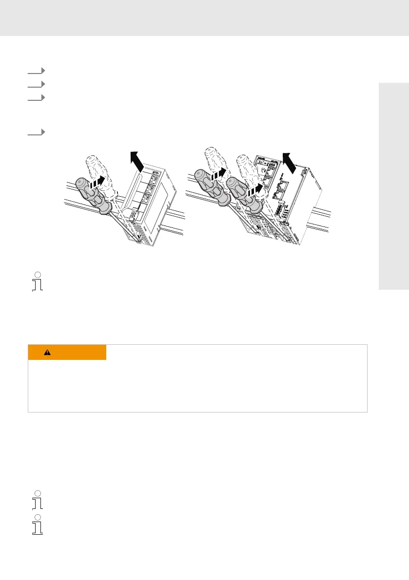
Removing the control from the top-hat rail
1. Remove the left or the right end clamp.
2. Remove the first ctrlX IO terminal from the ctrlX CORE
PLUS
if required.
3. Use a suitable tool (e.g. slotted screwdriver) and put it into the lower disengaging mechanism
(base latch) of the control and disengage the control (see (A) in the following figure). The base
latch is locked in the open position.
4. Remove the control vertically to the support rail [see (B)] in the following figure).
Fig. 12: Removing the control from the support rail
Before mounting the control on the support rail again, release the clamping of the open
position again. Press the locking lever, see Fig. 10.
10.5
Electric installation
10.5.1
External power supply unit
WARNING
Danger of lethal injury due to hazardous electric voltage
− Connect power supply units generating protective extra-low voltage (24
V) only to supply voltages designed for these power supply units. Note
the overvoltage categories (refer to the documentation of the power
supply unit).
− Do not apply the supply voltage to the protective extra-low voltage.
All control components are supplied from 24 V voltage supplies (SELV/PELV, NEC class 2).
The power supply units used have to be able to deliver the quadruple nominal current of the internal
and external fuses to ensure that the fuse reliably triggers in case of an error.
All lines of the 24 V voltage supply have to be routed separately from lines carrying higher voltages.
All peripherals, such as digital sensors or actuators connected to the interfaces of the control, also have
to comply with the criteria of safety-separated circuits.
The 24 V voltage supply can be grounded. For more detailed information, refer to the docu-
mentation of the power supply unit.
Use only power supply units that can bridge a half-wave failure (10 ms).
Mounting, dismounting and electric installation