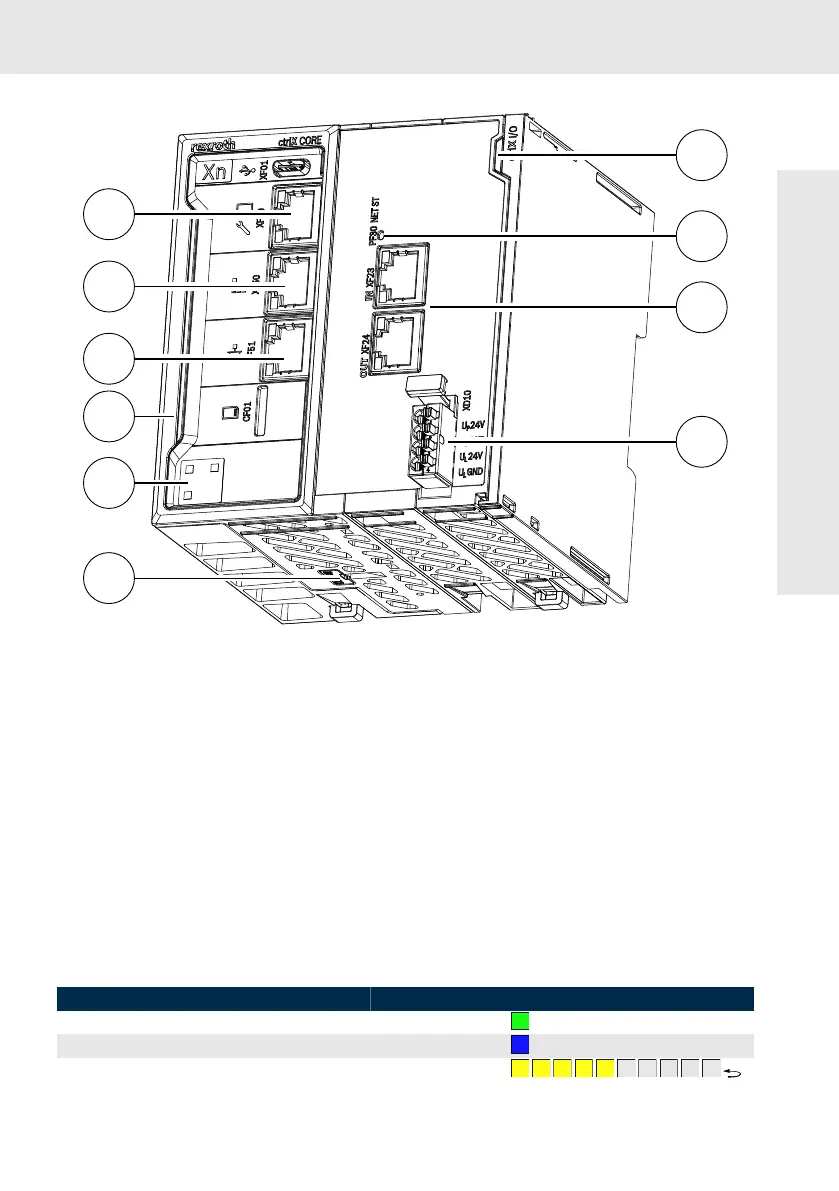
Fig. 19: Device view of the CORE
PLUS
①
HMI and engineering port
②
Field bus master (Ethercat)
③
1 GBit/s Ethernet (configurable)
④
ctrlX CORE status LED
⑤
QR code (references to the Bosch Rexroth
product catalog)
⑥
Battery case
➆
Device status LED
➇
PF30 NET ST LED
➈
Field bus slaves
➉
Voltage supply
12.2
Status displays
A status display on the front panel of the controls ctrlX CORE X2 and ctrlX CORE X3 is used for
error diagnostics. There are three status displays on the ctrlX CORE
PLUS
: The ctrlX CORE status LED,
PF30-NET-ST-LED and device status LED
The following functions are assigned to the ctlrX CORE status LED when the system firmware is running:
Table 12: Status LED
State Color
Control in "Run" state Green
Control in "Stop" state Blue
Warning in the ctrlX CORE Runtime Flashing yellow
Device description