– They have a counterpressure against the engaging forces when mounting
the modules in series to the control.
● Do not route cables parallel to motor cables or other strong interference sour-
ces to avoid coupling of interferences
● The LED displays may not be hidden
● Observe the bending radius of the cables used when routing the connecting
lines
● Use strain reliefs for all cables
● Keep the maximum distance possible from interference sources
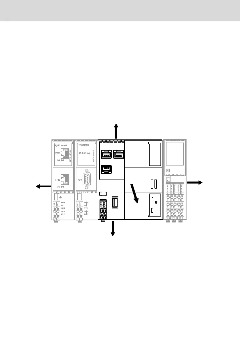
● Provide minimum distances for sufficient cooling. Refer to the operating in-
structions of the XM control, see fig. 10-3 "Minimum distances for the circula-
tion of ambient air" on page 18
30 mm
30 mm
100 mm
100 mm
122.7
126.3
100
30 mm
Fig. 10-3: Minimum distances for the circulation of ambient air
In case of a several line design, the supply air has to be measured under each
line and its limit value has to be observed. For information on ambient tem-
peratures, refer to chapter 6 "Ambient conditions" on page 7
● Additionally, provide sufficient distance for mounting, demounting, plugs and
cables
● Use only cables approved for temperatures of at least +60°C. In case of ambi-
ent temperatures above +55 C, use cables approved for temperatures of at
least +75°C.
Bosch Rexroth AG
Mounting, demounting and electric installationI
Extension Modules Profibus, RT-
Ethernet, Sercos, CAN
18/37
DOK-CONTRL-XFE**EXTMOD-IT04-EN-P

 Loading...


