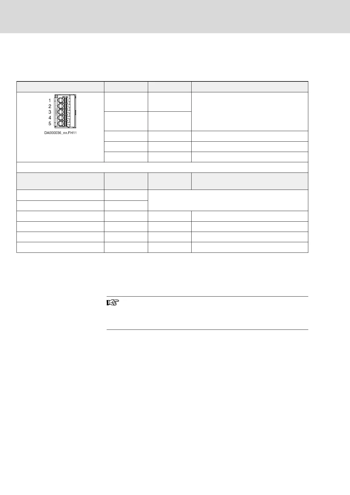
X52, Status Messages
Connection to the overall system
takes place via the drive connection box
KCU02.
View Connection Signal name Function
1 (TQ*) ______
E-Stop
Internal signals between KCU02 and KSM02/
KMS02
2 (VT*) _________
Module bus
3 (BN*) SI_Ch2 Internal connection X49.1 ↔ X52.3
4 (GN*) 0V_SI Internal connection X49.2 ↔ X52.4
5 (GY*) SI_Ch1 Internal connection X49.3 ↔ X52.5
Spring terminal (connector at hybrid
cable)
Unit Min. Max.
Connection cable stranded wire
mm
2
n.s.
Connection cable AWG
Voltage range V 0 24 +10%
Voltage level "H" V 15 n.s.
Voltage level "L" V n.s. 5
Output current mA n.s. 500
* Conductor color of the ready-made cable RKH
Tab. 12-8: Function, Pin Assignment, Properties
12.3.2 KSM02 connection points
Position of connection points
Use ready-made hybrid cables and terminal connectors by
Rexroth for X103.1 and X103.2.
X107 (programming module) is only accessible after the cover
has been removed.
Bosch Rexroth AG DOK-INDRV*-SI3-**VRS**-AP06-EN-P
Rexroth IndraDrive Integrated Safety Technology "Safe Torque Off" (as of MPx-16)
126/149
Project planning
LSA Control S.L. www.lsa-control.com comercial@lsa-control.com (+34) 960 62 43 01