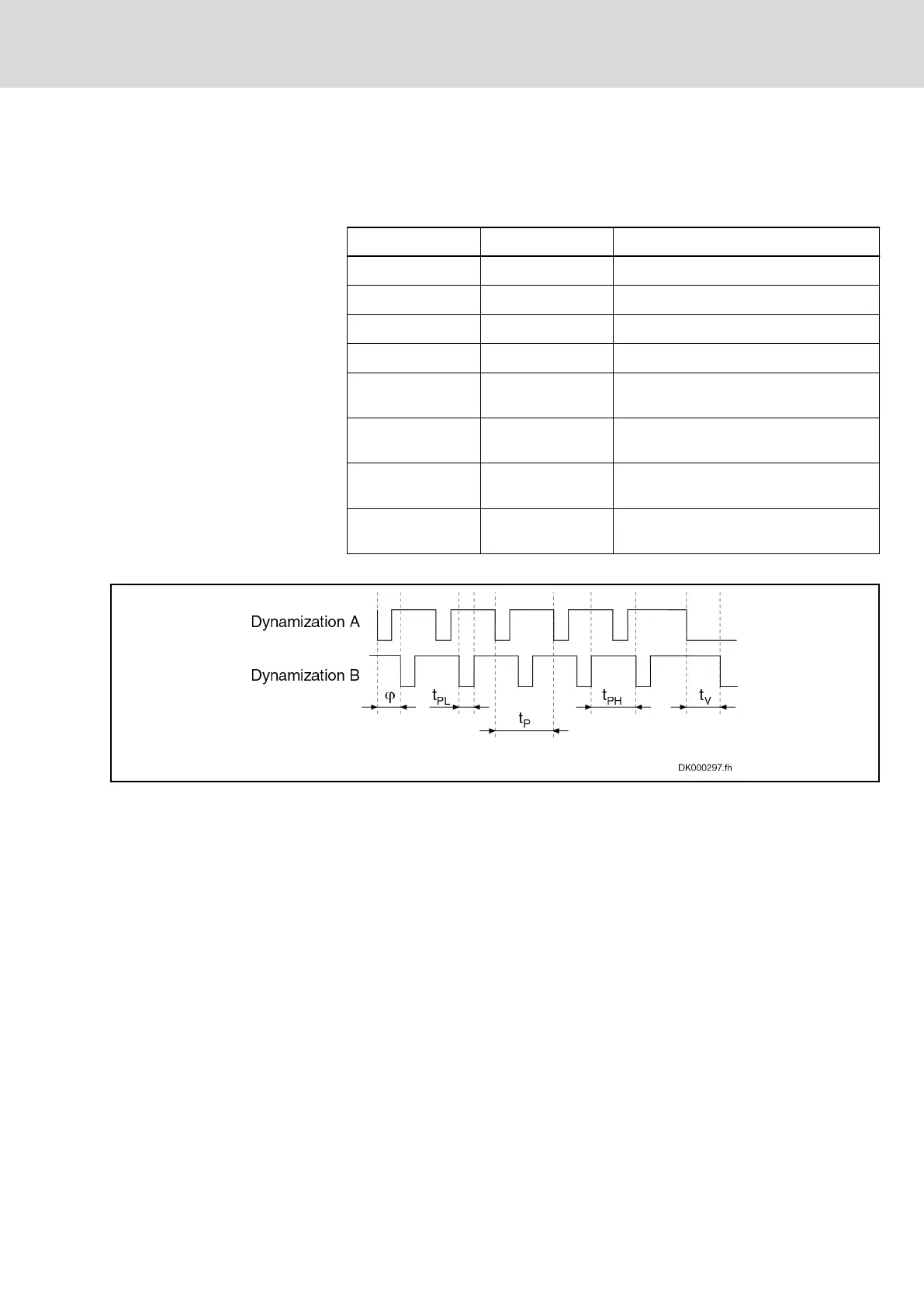
● Short circuit between both selection signals
In order that all other
relevant errors can be detected by the optional safety
technology modules "L3"/"L4", the dynamization pulses of the OSSD outputs
must comply with the following limit values:
Value Explanation
t
PLmax
1 ms Maximum low time of the test pulse
t
PLmin
20 µs Minimum low time of the test pulse
t
Pmax
1 h Maximum periodic time of the test pulses
t
Pmin
500 µs Minimum periodic time of the test pulses
t
Vmax
1 s
Maximum delay of the selection signals
for selection or deselection
t
Dmin
= t
PH
/ t
P
90 %
Minimum sampling ratio of the selection
signals
t
Bounce
400 ms
Maximum bounce time for a selection or
deselection
φ -
Phase shift of the test pulses on both
channels: No requirement
Tab. 5-1: Limit values of the dynamization pulses of the OSSD outputs
Fig. 5-2: Example of dynamized selection signals
The figure below illustrates, in schematic form, the interconnection of an
active safety unit and several drives with an "L option":
DOK-INDRV*-SI3-**VRS**-AP06-EN-P
Rexroth IndraDrive Integrated Safety Technology "Safe Torque Off" (as of MPx-16)
Bosch Rexroth AG 45/149
Functional principle of integrated safety technology
LSA Control S.L. www.lsa-control.com comercial@lsa-control.com (+34) 960 62 43 01