F 002 DG9 H00 2018-08-17| Bosch Automotive Service Solutions GmbH
30 | RG8.0 / RG4.0 | Operationen
6. Operation
6.1 Refrigerant recovery
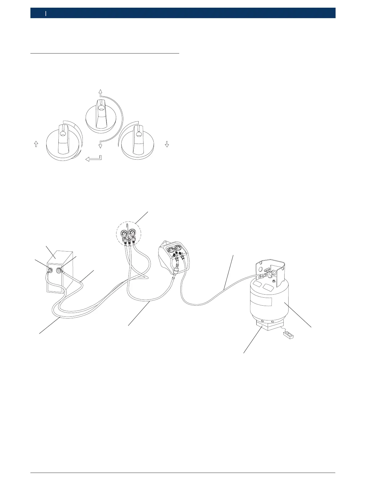
6.1.1 Valve positions for normal recovery
IN
VAPOUR
LIQUID
OPEN
CLOSED
CLOSED
RECOVER
PURGE
OUT
Fig. 2: Valve positions for normal recovery
6.1.2 Normal recovery
CL
OS
E
D
C
L
O
S
E
D
O
P
EN
V
APOUR
L
I
Q
UI
D
PURGE
R
E
COVER
IN
OUT
2
3
4
6
9
10
Fig. 3: Normal recovery
1 Liquid port/ High side port
2 A/Correfrigeration system
3 Vapour port / Low side port
4 Vapour/ Low side hose
5 Manifold gauge set with optional sight glass
6 Outlet hose.
7 Refrigerant tank.
8 Weighing scale
9 Inlet hose
10 Manguera de líquido/ lado alto
i The sight glass provides a method of determining the
state (liquid or vapour) of the system's refrigerant and
the presence of contamination in it
1. Disconnect the power supply to the A/Correfrigera-
tion system.
2. Connect the RG8.0 / RG4.0 to a mains power supply
that matches the voltage and frequency rating on the
RG8.0 / RG4.0.
3. Before making any hose connections, ensure that
A/C or refrigeration system service valves, manifold
gauge set valves, recovery unit control valves and
recovery tank valves are all in the closed position.
Also, make sure that the recovery / purge valve is in
the RECOVER position (pointed upwards). Refer to
Fig.2.