1 689 989 518 | 2022-07-24Robert Bosch GmbH
3.2 Overview SCT 418 and accessories
15
16
1
2
3
4
6
5
7
9
13
8
11
10
14
12
17
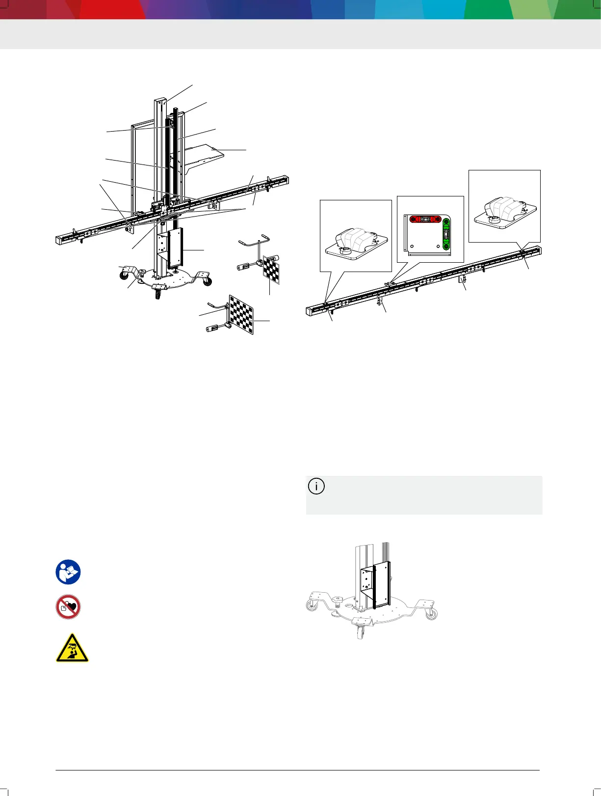
(1) Pillar with height adjustment of the indicator bar
(2) Alignment frame
(3) Ruler for height adjustment and locking device of the indicator
bar
(4) Shelf for laptop/tablet
(5) Indicator bar
(6) Slide for calibration boards (3x)
(7) Contact plate
(8) Brake (2x)
(9) Base plate
(10) Alignment unit
(11) Spirit levels for pitch and roll angles
(12) Retaining adapter X
(13) Mount for large calibration boards
(14) Calibration board retainer T
(15) Wheel holder with reference board CTA 400-x
(16) Wheel holder with reference board CTA 403-x
(17) Support clamp
---
3.3 Warnings and mandatory-action signs
on the product
All warning signs must be in legible condition.
Read and understand the operating instruc‐
tions before working with the SCT 418.
---
Individuals with a pacemaker or implanted
debrillator must maintain sucient distance
from the SCT 418.
---
Beware of the indicator bar at head height to
avoid injury.
---
3.4
Functional description
Alignment of SCT 418
The "Bosch ADAS Positioning" software will guide the
user through the alignment process for the SCT 418
step by step. The work steps depend on the selected
sensor, vehicle and accessories.
Front camera calibration
For front camera calibration using the SCT 418, the
CTA 2xx-x and CTA 3xx-x calibration boards are re‐
quired. The calibration boards must be attached to the
SCT 418 at the required height and positioned at the
required distance from the front of the vehicle. Use the
magnetic slide to attach the calibration boards to the
SCT 418.
---
3.5 Measuring bar
The calibration boards are attached to the measuring
bar during the calibration process. The two cameras
(A) for detecting the reference boards on the vehicle
are located at the outer edges of the measuring bar.
3 different positions (B) of the cameras allow detecting
the calibration boards in different vehicle positions.
The pitch angle (D) and the roll angle (C) can be read
via the spirit levels attached to the measuring bar.
Retaining brackets (E) for mounting the retaining
adapters X are used to attach large calibration boards
without a retaining plate.
The measuring bar can be moved to a vertical
parking position for space-saving storage. See
10 "Moving the indicator bar to parking position"
---
3.6 Contact plate
The contact plate is required for calibrations that have
the reference point on the front bumper. The rubber
pads ensure that there is no damage to the vehicle if it
comes into contact with the front bumper.
---
SCT 418 | 5 | en