17
DISASSEMBLY/ASSEMBLY PROCEDURES
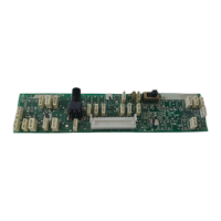
4. Main PCB Replacement
4.1 Orient the main PCB (8) so that the
connectors are aligned with the rear panel
of the amplifier chassis (16), and slide the
main PCB into place.
4.2 Secure the main PCB to the amplifier
chassis using the six screws (9) removed
in procedure 3.4.
4.3 Reconnect all connectors unplugged
in procedures 3.2 and 3.3.
4.4 Replace the top cover (2) using
procedure 2.
5. Amplifier Module Removal
5.1 Remove the top cover (2) using
procedure 1.
5.2 Unplug the appropriate cable
connector, (J7B or J8B), for the amplifier
module that you wish to remove.
5.3 Remove the two screws (12) that
secure the amplifier module to the amplifier
chassis (16) and lift the amplifier module
straight out.
6. Amplifier Module Replacement
6.1 Place the amplifier module into the
appropriate spot in the amplifier chassis
(16) and secure it using the two screws
(12) removed in procedure 5.3.
6.2 Plug the amplifier module cable into the
appropriate connector (J7B or J8B) on the
main PCB (8).
6.3 Replace the top cover (2) using
procedure 2.
1. Top Cover Removal
Note: Refer to Figures 3 and 4, as
applicable, for the following procedures.
Note: The numbers in the parentheses
correspond to the callouts in Figures 3
and 4.
1.1 Unplug the power cable from IEC
connector on the rear of the amplifier.
1.2 Using a phillips-head screwdriver,
remove the five screws (1) that secure the
top cover (2) to the amplifier chassis (16).
1.3 Lift the top cover straight off.
2. Top Cover Replacement
2.1 Observing orientation, place the top
cover (2) straight down onto the amplifier
chassis (16).
2.2 Using a phillips-head screwdriver,
secure the top cover to the amplifier
chassis using the five screws (1) that
were removed in procedure 1.
3. Main PCB Removal
3.1 Remove the top cover (2) using
procedure 1.
3.2 Unplug all of the cable connectors from
the rear panel of the amplifier.
3.3 On the main PCB (8), unplug the
connectors at J2, J7B, J3, J8B, J602, J601,
J400, J401, and J600.
3.4 Using a phillips-head screwdriver,
remove the six screws (9) that secure the
main PCB to the amplifier chassis (16).
3.5 Lift the main PCB at the edge nearest
the amplifier heatsinks, and slide the PCB
forward, until the main PCB connectors
clear the amplifier rear panel, then lift the
PCB straight up.