21
AMPLUS™ 100 TEST SETUP PARAMETERS
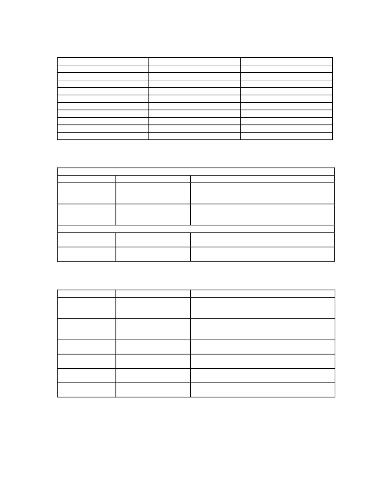
Table 2. AmPlus 100 Initial Switch Settings
Table 3. AmPlus 100 Signal Inputs Table
Table 4. AmPlus 100 Signal Outputs Table
Control Name Reference Designator Default Setting
Input Mode S1 switch Left (2-Channel/stereo)
Source Trim - Channel 1 R1 potentiometer CW (no attenuation)
Source Trim - Channel 2 R2 potentiometer CW (no attenuation)
Zone 2 Trim R3 potentiometer CW (no attenuation)
Bass Adjust - Channel 1 R4 potentiometer CW (full gain)
Bass Adjust - Channel 2 R5 potentiometer CW (full gain)
High Pass Filter S4 switch left (HPF off)
Remote Volume Setup S5 switch left (1 remote)
Source Mix S7 switch left (2 - channel)
Amp Mode S6 switch left (70V/100V mode)
Function PCB Location Type
Line Output
(Channel 1)
J5 (Pins 1, 2, and 3) Impedance-balanced: tie LO to the (-) pin and
the HI to the (+) pin. Tie the source shield pin
to the ground terminal.
Line Output
(Channel 2)
J5 (Pins 3, 4, and 5) Impedance-balanced: tie LO to the (-) pin and
the HI to the (+) pin. Tie the source shield pin
to the ground terminal.
Power Amplifier
70V/100V (CV)
J6 (Pins 1 and 2) Balanced; connect LO to the (-) pin and HI to
the (+) pin.
Power Amplifier
4Ω/Channel 1
J6 (Pins 3 and 4) Unbalanced: connect LO to the (-) pin and HI
to the (+) pin.
Power Amplifier
4Ω/Channel 2
J6 (Pins 5 and 6) Unbalanced: connect LO to the (-) pin and HI
to the (+) pin.
Power Amplifier
XFR (center tap)
J6 (Pins 7 and 8) Jumper; short J6-7 and J6-8
Balanced Inputs
Function Location Type
Source Input
(Channel 1)
(J1) Pins 1, 2, and 3 Connect source LO pin to the (-) terminal and
source HI pin to the (+) terminal. Tie the
source shield to the ground terminal.
Source Input
(Channel 2)
(J1) Pins 3, 4, and 5 Connect source LO pin to the (-) terminal and
source HI pin to the (+) terminal. Tie the
source shield to the ground terminal.
Unbalanced (Single-ended) Inputs
Source Input
(Channel 1)
(J1) Pins 1, 2, and 3 Connect source HI pin to the (+) terminal and
source ground to the (-) terminal.
Source Input
(Channel 2)
(J1) Pins 3, 4, and 5 Connect source HI pin to the (+) terminal and
source ground to the (-) terminal.