26
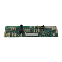
Table 8. AmPlus 50 Initial Switch Settings
AMPLUS™ 50 TEST SETUP PARAMETERS
Table 9. AmPlus 50 Signal Inputs Table
Table 10. AmPlus 50 Signal Outputs Table
Control Name Reference Designator Default Setting
Source Trim - Channel 1 R1 potentiometer CW (no attenuation)
Source Trim - Channel 2 R2 potentiometer CW (no attenuation)
Bass Adjust R4 potentiometer CW (full gain)
High Pass Filter S4 switch Left (HPF OFF)
Amp Mode S6 switch Left (70V/100V mode)
Function PCB Location Type
Power Amplifier
70V/100V (CV)
J6 (Pins 1 and 2) Balanced; connect LO to the (-) pin and HI to
the (+) pin.
Power Amplifier
4Ω/Channel 1
J6 (Pins 3 and 4) Unbalanced: connect LO to the (-) pin and HI
to the (+) pin.
Balanced Inputs
Function Location Type
Source Input
(Channel 1)
(J1) Pins 1, 2, and 3 Connect source LO pin to the (-) terminal and
source HI pin to the (+) terminal. Tie the
source shield to the ground terminal.
Source Input
(Channel 2)
(J1) Pins 3, 4, and 5 Connect source LO pin to the (-) terminal and
source HI pin to the (+) terminal. Tie the
source shield to the ground terminal.
Unbalanced (Single-ended) Inputs
Source Input
(Channel 1)
(J1) Pins 1, 2, and 3 Connect source HI pin to the (+) terminal and
source ground to the (-) terminal.
Source Input
(Channel 2)
(J1) Pins 3, 4, and 5 Connect source HI pin to the (+) terminal and
source ground to the (-) terminal.