25
AMPLUS™ 100 TEST PROCEDURES
12.5 Measure the output at the Channel 1
4Ω Speaker Outputs. It should be
-45dBV +5.0dBV.
12.6 Measure the output at the Channel 2
4Ω Speaker Outputs. It should be
-45dBV +5.0dBV.
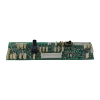
12.7 On the main PCB, place the Remote
Zone Assign switch (S5) to the 2 Remotes
position.
12.8 Measure the output at the Channel 2
4Ω Speaker Outputs. It should be
-45dBV +5.0dBV.
13. D.C. Offset Test
13.1 Set up the unit under test as listed in
the Test Setup Notes section.
13.2 With both inputs terminated, and with
no signal applied, measure the D.C.
voltage at the Channel 1 and 2, 4Ω
Speaker Outputs.
13.3 It should be 0mVDC ± 10mVDC for
both channels.
10.3 Reference a dB meter to the output
level. This is the reference level.
10.4 Perform the 20Hz and 100Hz tests as
listed in Table 7.
Note: The following test is for channel 1
only, there is no high pass filter circuit for
channel 2.
11. Channel 1 High Pass Filter Test
11.1 Set up the unit under test as listed in
the Test Setup Notes section.
11.2 On the main PCB, place the High
Pass Filter switch (S4) to the HPF IN
position.
11.3 Apply a 31.5mVrms, 1kHz signal to the
Channel 1 Source Input.
11.4 Reference a dB meter to this output
level.
11.5 Apply a 31.5mVrms, 50Hz signal to
the Channel 1 Source Input.
11.6 Measure the output at Channel 1.
It should be -22.0dBr ± 3dB (balanced
inputs), or +12.5dBr ± 3dB (unbalanced
inputs).
12. Remote Volume Attenuation Test
12.1 Set up the unit under test as listed in
the Test Setup Notes section.
12.2 Place a jumper from J4-1 to J4-2 and
from J4-2 to J4-3. This will apply full
attenuation to the VCA's for both channel
1 and 2.
12.3 On the main PCB, place the Remote
Zone Assign switch (S5) in the 1 Remote
position.
12.4 Apply a 280mVrms, 1kHz signal to the
channel 1 and 2 Source Inputs.