22
AMPLUS™ 100 TEST PROCEDURES
Test Setup Notes:
1. This amplifier is designed to be used
with balanced inputs at J1. If you have a
signal generator capable of supplying a
balanced input, refer to the balanced inputs
info in Table 3. If you can only drive the
amplifier using unbalanced (single-ended)
inputs, refer to the the unbalanced inputs
info in Table 3. Also refer to the appropriate
information (balanced or unbalanced) for
output levels in the various tables and text.
2. Before testing, make sure you have the
connectors for the inputs and outputs at J1,
J4, J5, and J6. The part number for the
connector kit that includes J1, J4, and J5 is
188620-001. The part number for the J6
connector is 190694-008 for the AmPlus
100 amplifier.
3. Be sure to set the unit switch positions in
accordance with Table 2. AmPlus 100 Initial
Switch Settings, before testing.
4. All tests are to be performed with option
cards and eq cards removed.
5. Definition of Signal Paths:
The five signal paths that are used during
testing are:
1. Source Input 1 to Line Output 1
2. Source Input 2 to Line Output 2
3. Source Input 1 to Speaker
Output 1 (4Ω).
4. Source Input 2 to Speaker
Output 2 (4Ω).
5. Source Input 1 and 2 (summed
internally) to 70/100V Output.
6. For the following tests, refer to Tables 3
and 4 for Signal Input and Signal Output
connections.
7. For Gain, Response, and Distortion
tests, the unit shall be driven from a 600Ω
source, and measured across a 10kΩ,
1/4 W resistor terminated across the (+)
and ground terminals at the Line Outputs,
and across the Speaker Output with a
98Ω, 100W load across the 70/100V
outputs.
8. Unless otherwise noted, the remote
volume inputs (J4-1 to J4-2 and J4-3 to
J4-2) are to be terminated with a 10kΩ
resistor.
9. Input Voltage Reference shall be
the actual input voltage present at the
input, not the open circuit generator output.
1. Gain Test;
Source Input to Line Output
1.1 Apply a 100mVrms, 1kHz signal to the
Channel 1 and 2 Source Inputs.
1.2 Reference a dB meter to the
input level.
1.3 Measure the output level at the
Channel 1 and 2 Line Outputs.
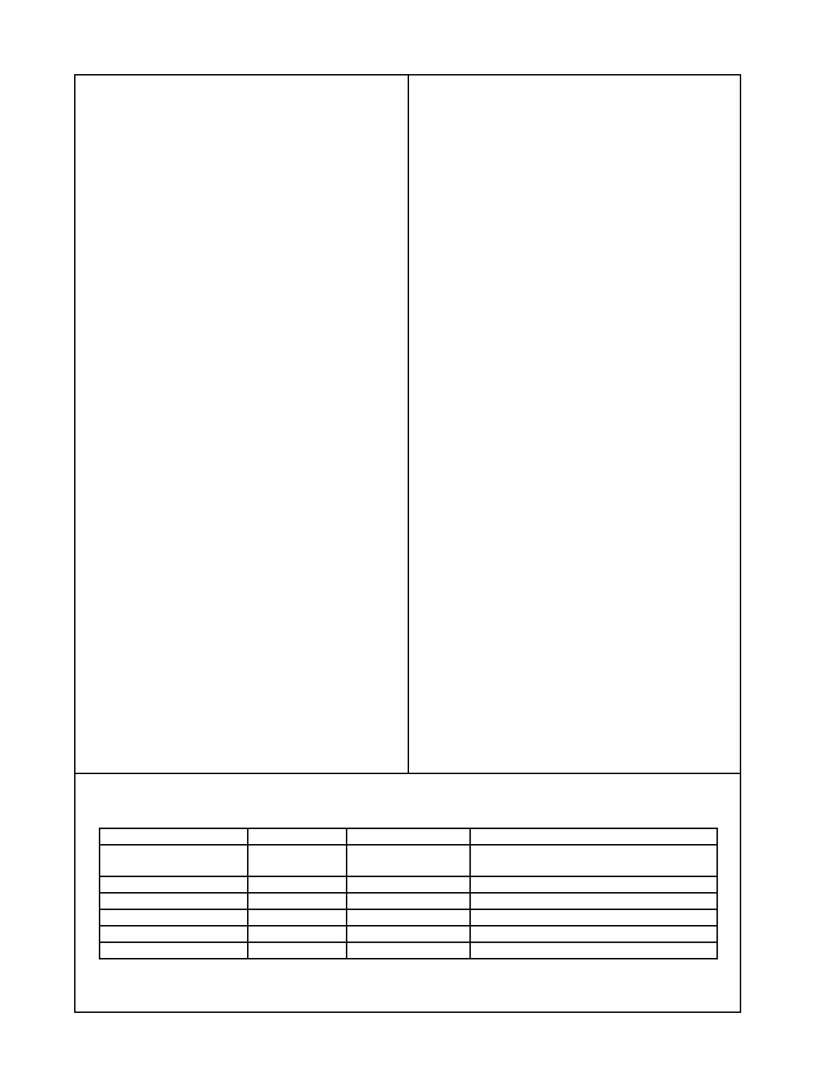
Table 5. Source Input to 70/100V Speaker Output Test Table
Test Freq. Input (J1) Output (J6)
Gain 1kHz 1 kHz 31.5 mVrms 7.5Vrms± 0.75V (187915-1)
11.0Vrms±0.75V (187915-2)
Response 1kHz 1 kHz (Ref) 31.5 mVrms 0dBr ± 0.1dB
Response 60 Hz 60 Hz 31.5 mVrms +9.3dBr ± 1.0dB
Response 10 kHz 10 kHz 31.5 mVrms -0.25dBr ± 1.0dB
THD 1 kHz 31.5 mVrms 0.2% + 0.8%
Noise none none -50dBV + 10.0dBV