47
Test Procedures
Note: The following tests will check the
performance of the Power Supply / Amplifier
PCB assembly
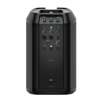
7. Channel 1 Line Array Amplifier
THD+N Test
7.1 Set the channel 1 volume, bass and
treble tone controls to the 12 o’clock setting
(straight up).
7.2 Connect a 4 Ohm, 50 Watt load resistor
to the line array output.
7.3 Apply a balanced 1kHZ, -50dBV
(3.16mVrms) sine wave to the channel 1
microphone XLR input jack.
7.4 Measure the THD+N level. It should be
< 1%.
8. Power Amplifier Gain and THD+N Test
Note: During these high power tests, take
care to not operate the amplifer for a long
period of time to avoid overheating the
amplifier output IC.
8.1 Set the channel 2 ToneMatch switch to
OFF.
8.2 Set the channel 2 volume control to the
12 o’clock setting.
8.3 Verify that the AC line cord is not con-
nected to the unit under test. On the back of
the power stand, remove the 6 screws that
secure the rear cover. Lift off the cover.
Remove the 4 screws that secure the power
supply / power amplifier PCB to the power
stand. Slide the PCB down and out of the
power stand so that the component side of
the board is facing upward.
8.4 Connect a 4 Ohm, 50 Watt load resistor
to pins 1 and 2 the high frequencey array
output connector CN1.
8.5 Connect a 4 Ohm, 50 Watt load resistor
to pins 1 and 2 of the bass amplifier output
connector CN2. These connectors are
located near the bottom of the PCB assem-
bly.
8.6 Re-connect the AC line cord and turn on
the power stand at the AC power switch.
8.7 Apply a balanced 1kHZ, 0dBV (1Vrms)
sine wave to the channel 2 balanced 1/4”
input jack.
8.8 Reference a dB meter to the input level.
Measure the output gain level at the line
array’s 4 ohm load resistor. It should be
+28.4dBr minimum.
8.9 Measure the THD+N level. It should be
< 1%.
8.10 Apply a balanced 100 Hz, 0dBV (1Vrms)
sine wave to the channel 2 balanced 1/4”
input jack.
8.11 Reference a dB meter to the input level.
Measure the output gain level at the
woofers’s 4 ohm load resistor. It should be
+28.4dBr minimum.
8.12 Measure the THD+N level. It should be
< 1%.
8.13 Re-install the power supply / power
amplifier PCB assembly into the power
stand. Replace the rear cover. Perform the
system sweep test below to ensure there
are no air leaks in the power stand.
9. System Sweep Test
9.1 Set up the system in the collapsed
position.
9.2 Set the channel 2 ToneMatch switch to
the OFF position (down). Set the channel 2
volume control to maximum.
9.3 Apply a 50 Hz, -34dBV (20mVrms) sine
wave to both of the channel 2 RCA input
jacks.
 Loading...

