50
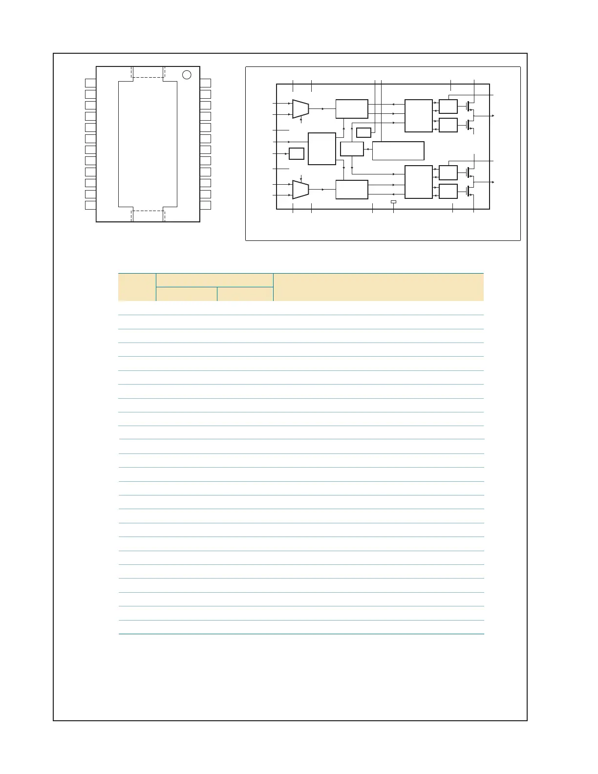
Pin Description
Pin Configuration
TDA8920BTH
V
SSD
V
SSA2
V
DDP2
SGND2
V2TOOB
DDA2
M2NI2TUO
V
SSP2
IN2P
EDOM.c.n
CSOIBATS
V
SSP1
IN1P
M1NI1TUO
V1TOOB
DDA1
V
DDP1
SGND1
VTORP
SSA1
24
23
22
21
20
19
18
17
16
15
14
13
11
12
9
10
7
8
5
6
3
4
1
2
Symbol Pin Description
TDA8920BTH TDA8920BJ
V
SSA2
1 18 negative analog supply voltage for channel 2
SGND2 2 19 signal ground for channel 2
V
DDA2
3 20 positive analog supply voltage for channel 2
IN2M 4 21 negative audio input for channel 2
IN2P 5 22 positive audio input for channel 2
MODE 6 23 mode selection input: Standby, Mute or Operating mode
OSC 7 1 oscillator frequency adjustment or tracking input
IN1P 8 2 positive audio input for channel 1
IN1M 9 3 negative audio input for channel 1
V
DDA1
10 4 positive analog supply voltage for channel 1
SGND1 11 5 signal ground for channel 1
V
SSA1
12 6 negative analog supply voltage for channel 1
PROT 13 7 decoupling capacitor for protection (OCP)
V
DDP1
14 8 positive power supply voltage for channel 1
BOOT1 15 9 bootstrap capacitor for channel 1
OUT1 16 10 PWM output from channel 1
V
SSP1
17 11 negative power supply voltage for channel 1
STABI 18 12 decoupling of internal stabilizer for logic supply
n.c. 19 - not connected
V
SSP2
20 13 negative power supply voltage for channel 2
OUT2 21 14 PWM output from channel 2
BOOT2 22 15 bootstrap capacitor for channel 2
V
DDP2
23 16 positive power supply voltage for channel 2
V
SSD
24 17 negative digital supply voltage
Pin numbers in parenthesis refer to the TDA8920BJ.
coa023
OUT1
V
SSP1
V
DDP2
DRIVER
HIGH
OUT2
BOOT2
TDA8920BTH
(TDA8920BJ)
BOOT1
DRIVER
LOW
RELEASE1
SWITCH1
ENABLE1
CONTROL
AND
HANDSHAKE
PWM
MODULATOR
MANAGER
OSCILLATOR
TEMPERATURE SENSOR
CURRENT PROTECTION
VOLTAGE PROTECTION
STABI
MODE
INPUT
STAGE
mute
9 (3)
8 (2)
IN1M
IN1P
22 (15)
21 (14)
20 (13)
17 (11)
16 (10)
15 (9)
V
SSP2
V
SSP1
DRIVER
HIGH
DRIVER
LOW
RELEASE2
SWITCH2
ENABLE2
CONTROL
AND
HANDSHAKE
PWM
MODULATOR
11 (5)
SGND1
7 (1)
OSC
2 (19)
SGND2
6 (23)
MODE
INPUT
STAGE
mute
5 (22)
4 (21)
IN2M
IN2P
19 (-)24 (17)
V
SSD
n.c.
1 (18)
V
SSA2
12 (6)
V
SSA1
3 (20)
V
DDA2
10 (4)
V
DDA1
23 (16)13 (7) )8( 41)21( 81
V
DDP2
PROTSTABI
V
DDP1
Block Diagram
IC Diagrams
TDA8920BTH-N2 Power Amplifier

 Loading...