17
19
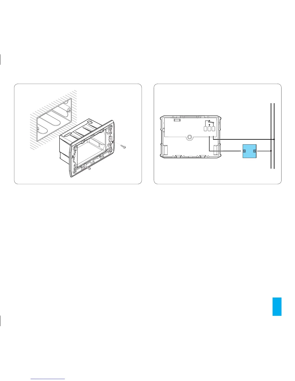
• Electrical connections are to made within the back-box
terminal block as indicated in either diagram 20 or 21.
• Paying attention to the UP direction indication use the
screws supplied to mount the unit to the back-box (fig.
19).
• Push the main unit of the thermostat all the way to the
back and then fit the surround.
Insert the locking tab L.
2 ELECTRICAL CONNECTIONS
The wiring will depend on the type of equipment to be
controlled by the thermostat: refer to the diagram in fig.
20 or 21.
KEY
Mains power supply wires
N = neutral
L = live
Relay contacts
C = common
NA = normally open contact
NC = normally closed contact