2 3 Wiring Precautions2 3 Wiring Precautions
Before wiring, verify the label for correct model number and options. Switch
off the power while checking.
Care must be taken to ensure that maximum voltage rating specified on the
label are not exceeded.
It is recommended that power of these units to be protected by fuses or circuit
breakers rated at the minimum value possible.
All units should be installed inside a suitably grounded metal enclosure to
prevent live parts being accessible from human hands and metal tools.
All wiring must conform to appropriate standards of good practice and local
codes and regulations. Wiring must be suitable for voltage, current, and
temperature rating of the system.
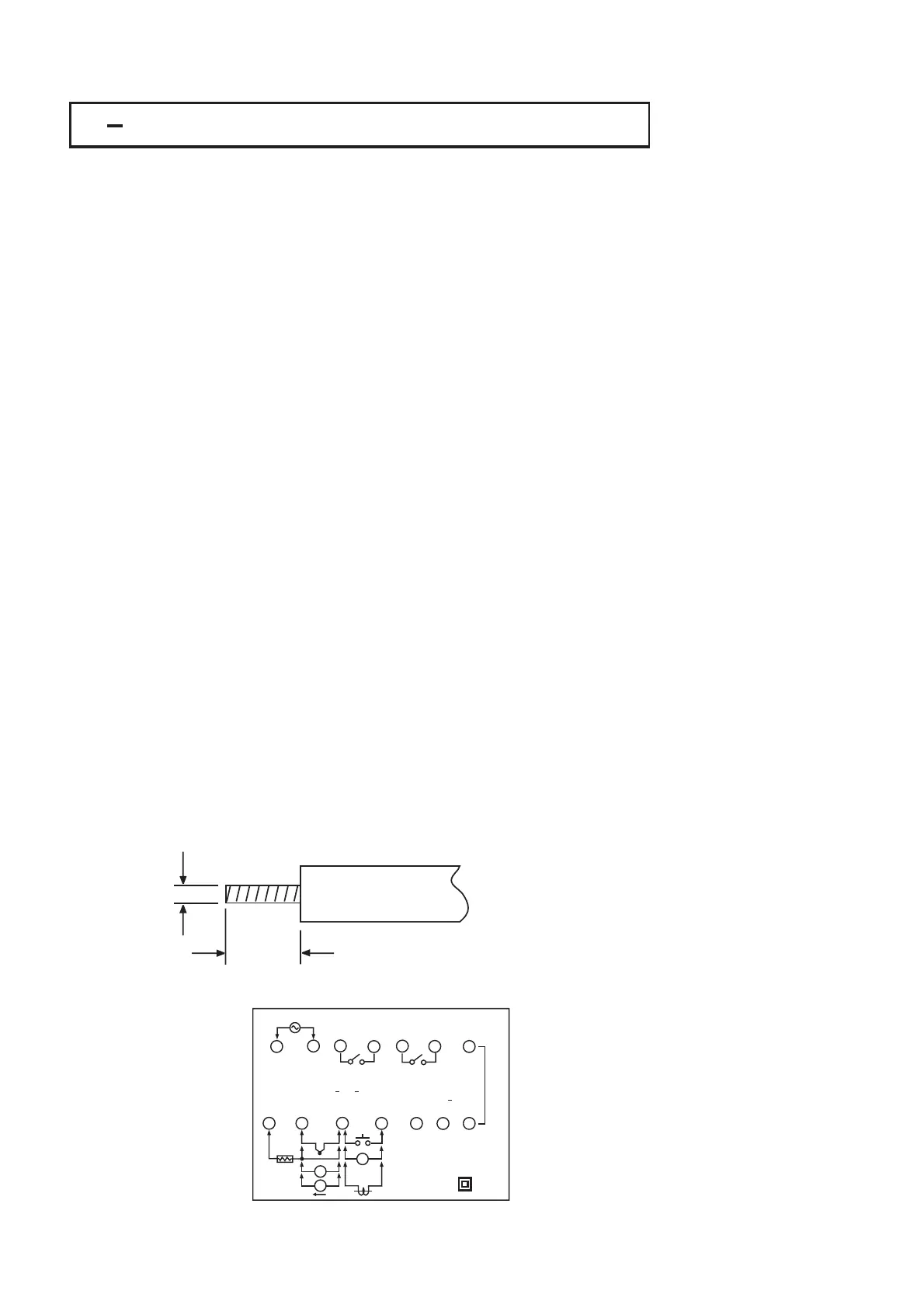
The " stripped " leads as specified in Figure 2.2 below are used for power and
sensor connections.
Beware not to over-tighten the terminal screws.
Unused control terminals should not be used as jumper points as they may
be internally connected, causing damage to the unit.
Verify that the ratings of the output devices and the inputs as specified in
Chapter 8 are not exceeded.
Electric power in industrial environments contains a certain amount of noise in
the form of transient voltage and spikes. This electrical noise can enter and
adversely affect the operation of microprocessor-based controls. For this
reason we strongly recommend the use of shielded thermocouple extension
wire which connects the sensor to the controller. This wire is a twisted-pair
construction with foil wrap and drain wire. The drain wire is to be attached to
ground at one end only.
Before wiring, verify the label for correct model number and options. Switch
off
the power while checking.
Care
must be taken to ensure that maximum voltage rating specified on the
label
are not exceeded.
It
is recommended that power of these units to be protected by fuses or circuit
breakers
rated at the minimum value possible.
All
units should be installed inside a suitably grounded metal enclosure to
prevent
live parts being accessible from human hands and metal tools.
All
wiring must conform to appropriate standards of good practice and local
codes
and regulations. Wiring must be suitable for voltage, current, and
temperature
rating of the system.
The
" stripped " leads as specified in Figure 2.2 below are used for power and
sensor
connections.
Beware
not to over-tighten the terminal screws.
Unused
control terminals should not be used as jumper points as they may
be
internally connected, causing damage to the unit.
Verify
that the ratings of the output devices and the inputs as specified in
Chapter
8 are not exceeded.
Electric
power in industrial environments contains a certain amount of noise in
the
form of transient voltage and spikes. This electrical noise can enter and
adversely
affect the operation of microprocessor-based controls. For this
reason
we strongly recommend the use of shielded thermocouple extension
wire
which connects the sensor to the controller. This wire is a twisted-pair
construction
with foil wrap and drain wire. The drain wire is to be attached to
ground
at one end only.
4.5 7.0 mm
0.18" 0.27"
~
~
2.0mm
0.08" max.
Figure 2.2 Lead TerminationFigure 2.2 Lead Termination
Figure 2.3 Rear Terminal
Connection Diagram
Figure 2.3 Rear Terminal
Connection
Diagram
*
*
*
*
*
*
*
*
*
*
22
UM25001C
+
+
+
_
_
_
RTD
A
+
+
+
+
V+ ,CT+
EI+,COM
TC+
_
_
_
_
B
PTB PTB
V,CT
__
EI ,TC
B
CT
PTA
AO+
AO
TX1 TX2
90-264 VAC
47-63 Hz,15VA
OUT2
ALM2
2A/240 VAC 2A/240 VAC
ALM1(LOGIC OUTPUT)
L
N
ALM1
OUT1
ALM1
CAT.IICAT. I I
1
8 9
10
11
12 13 14
2
3
4
5
7
6
V
I
V