UM25001C
77
4 9 Analog Retransmission4 9 Analog Retransmission
The Analog Retransmission is available for model number BTC-2500-XXXXXN
Where N 3,4 or 5. See Ordering Code in= section 1-2.
The Analog Retransmission is available for model number BTC-2500-XXXXXN
Where
N3,4or 5. See Ordering Code in= section 1-2.
Setup
Select FULL for FUNC in the setup menu.
COMM selects a correct output signal which should be accordant with the
retransmission option used. Five types of retransmission output are available.
These are : 4-20 mA, 0-20mA, 0-5V, 1-5V and 0-10V. There are 8 types of
parameters that can be retransmitted according to the Analog Function (
AOFN ) selected. These are : PV1, PV2, PV1 PV2, PV2 PV1, SV, MV1, MV2
and PV SV. Refer to for a complete description. AOLO selects a
value corresponding to output zero and AOHI selects a value corresponding
to output SPAN.
Table 1.4
Select FULL for FUNC in the setup menu.
COMM
selects a correct output signal which should be accordant with the
retransmission
option used. Five types of retransmission output are available.
These
are : 4-20 mA, 0-20mA, 0-5V, 1-5V and 0-10V. There are 8 types of
parameters
that can be retransmitted according to the Analog Function (
AOFN
) selected. These are : PV1, PV2, PV1 PV2, PV2 PV1, SV, MV1, MV2
and
PV SV. Refer to for a complete description. AOLO selects a
value
corresponding to output zero and AOHI selects a value corresponding
to
output SPAN.
Table
1.4
Setup MenuSetup Menu
FUNC
COMM
AOFN
AOLO
AOHI
FUNC
COMM
AOFN
AOLO
AOHI
Terminals
12
13
AO+AO+
AO
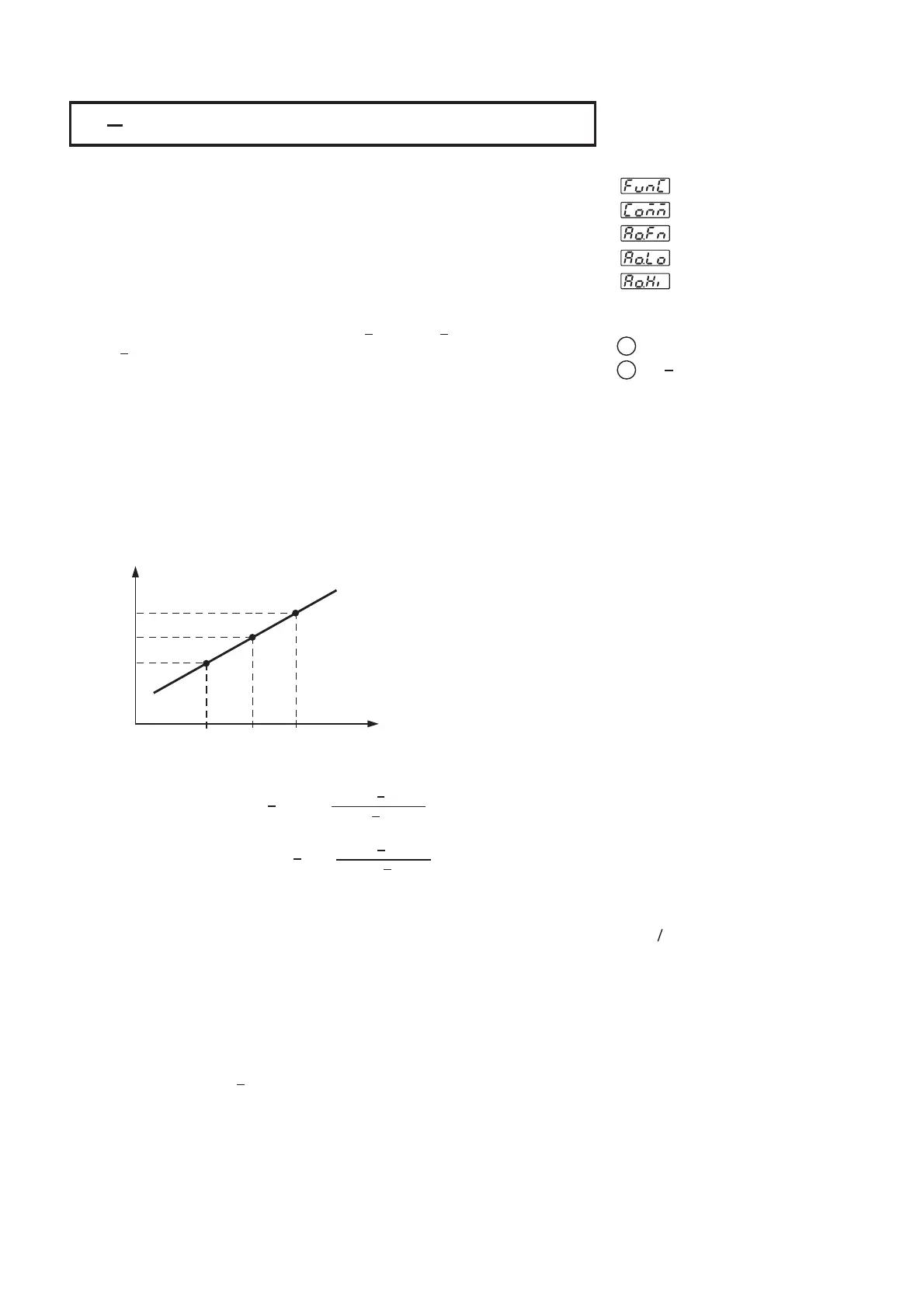
How to Determine Output Signal:How to Determine Output Signal:
AOLO and AOHI are set to map to output signal LOW SL ( e.g. 4mA ) and
output signal High SH ( e.g. 20mA ) respectively. The analog output signal
AOS corresponding to an arbitrary value of parameter AOV is determined by
the following curve.
AOLO and AOHI are set to map to output signal LOW SL ( e.g. 4mA ) and
output
signal High SH ( e.g. 20mA ) respectively. The analog output signal
AOS
corresponding to an arbitrary value of parameter AOV is determined by
the
following curve.
Parameter ValueParameter Value
Output
Signal
Output
Signal
SH
AOS
SL
AOLO AOV AOHI
Figure 4.6
Conversion Curve
for Retransmission
Figure 4.6
Conversion
Curve
for
Retransmission
Formula:
AOS=SL ( AOV AOLO )+AOS=SL ( AOV AOLO )+
SH SLSH SL
AOHI AOLOAOHI AOLO
AOV=AOLO ( AOS SL )+AOV=AOLO ( AOS SL )+
SH SLSH SL
AOHI AOLOAOHI AOLO
Notes:
Example
NOTES
The setup values used for AOHI and AOLO must not be equal, otherwise,
incorrect value will happen. However, AOHI can be set either higher or lower
than AOLO. If AOHI is set higher than AOLO it could result in a direct
conversion. If AOHI is set lower than AOLO it could result in a reverse
conversion.
The setup values used for AOHI and AOLO must not be equal, otherwise,
incorrect
value will happen. However, AOHI can be set either higher or lower
than
AOLO. If AOHI is set higher than AOLO it could result in a direct
conversion.
If AOHI is set lower than AOLO it could result in a reverse
conversion.
AOHI AOLO:
Reverse Conversion
<AOHI AOLO:
Reverse
Conversion
<
AOHI AOLO
AOHI AOLO:
Direct Conversion
=
>
AOHI AOLO
AOHI AOLO:
Direct
Conversion
=
>
A control uses 4-20 mA analog output to retransmit difference value between
input 1 and input 2 ( PV1 PV2 ). It is required that if the difference value is -
100, 4mA will be exported, and if the difference value is 100, 20mA will be
exported. Make the following Setup for BTC-2500:
IN1U PU, DP1 NODP, IN2U PU, DP2 NODP, FUNC FULL, COMM 4-20,
AOFN P1-2, AOLO -100, AOHI 100
== == = =
===
A control uses 4-20 mA analog output to retransmit difference value between
input
1 and input 2 ( PV1 PV2 ). It is required that if the difference value is -
100,
4mA will be exported, and if the difference value is 100, 20mA will be
exported.
Make the following Setup for BTC-2500:
IN1U PU,
DP1 NODP, IN2U PU, DP2 NODP, FUNC FULL, COMM 4-20,
AOFN P1-2,
AOLO -100, AOHI 100
== == = =
===
 Loading...