6
-
72
42hW-201601
CHAPTER 6 HYDRAULIC SYSTEM 3015R(h)/3515R(h)/4015R(h)/F36R(h)/F42R(h) TRACTOR
K20W6A11A
K20W6A12A
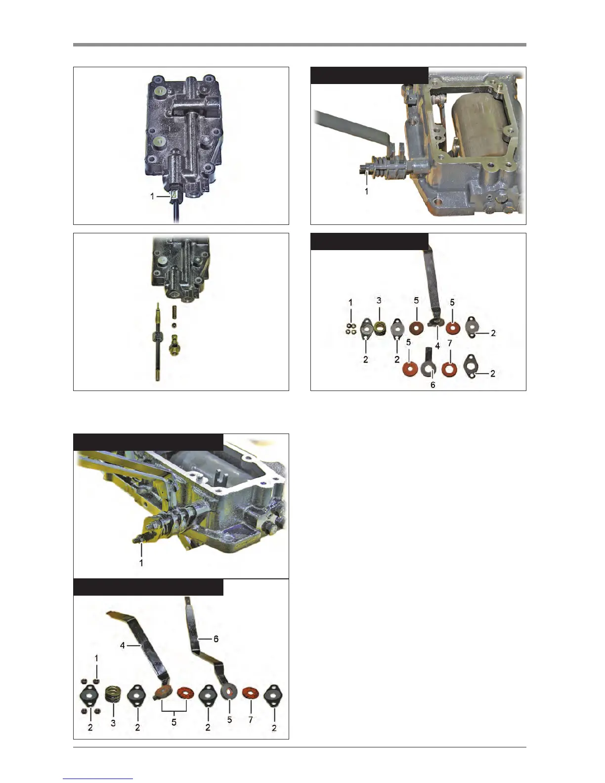
7. Remove the lower ing speed control valve
assembly (1).
K20W6A13A
POSITION/DRAFT CONTROL TYPE
K20W6A14A
POSITION/DRAFT CONTROL TYPE
K42W620A
POSITION CONTROL TYPE
K42W621A
POSITION CONTROL TYPE
8. Unscrew the lever retaining nut (1). Then, remove
the bracket A (2), spring (3), bracket A (2), plate
(5), P lever (4), plate (5), bracket A (2), plate (5), D
lever (6), friction plate (7) and bracket (2) in order.