16 Elan 10 2.0 / Elan 16 2.0 / Elan 25 2.1 Revision D
&KDSWHU'LVSOD\OD\RXW
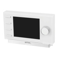
6.2 Operating mode
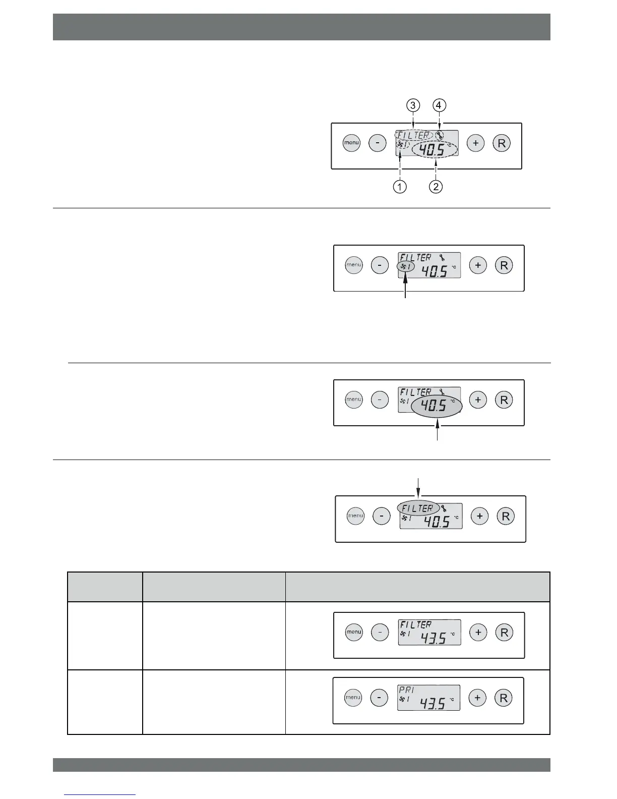
In operating mode, the display may simultaneously show 4 dif-
IHUHQWVLWXDWLRQVYDOXHV
1 = Status fan situation, (see § 6.2.1
2 = Output temperature (see § 6.2.2
3 = Message textHJWH[W¿OWHUVLWXDWLRQsee § 6.2.3
4 = Fault symbol (see § 8.1 and § 8.2
The current temperature of the output air temperature is
displayed here.
This part of the display shows a fan symbol together with
a number.
The fan symbol is visible when the system fan is running.
When the system fan is stopped, the fan symbol is not vi-
sible.
The number behind the fan symbol indicates the fan mode.
A 1 is shown here by default; when a ventilation switch is
connected, numbers 2 or 3 or no value may be indicated
here; Refer to section 5.11.2 for an explanation of the num-
bers.
6.2.1 Status system fan
6.2.2 Display output temperature
This part of the display may show a message text. The
message text “Filter” always takes precedence over the
other message texts.
The following message texts may appear during operating
mode.
6.2.3 Message text for operating mode
Message text
on display
Description
FILTER When the text “FILTER” appears
RQWKHGLVSOD\WKH¿OWHUPXVWEH
cleaned or replaced; for detailed in-
formation on this subject see § 9.1.
PR1 The Elan appliance is set to the
outdoor air programme
 Loading...