26 Elan 10 2.0 / Elan 16 2.0 / Elan 25 2.1 Revision D
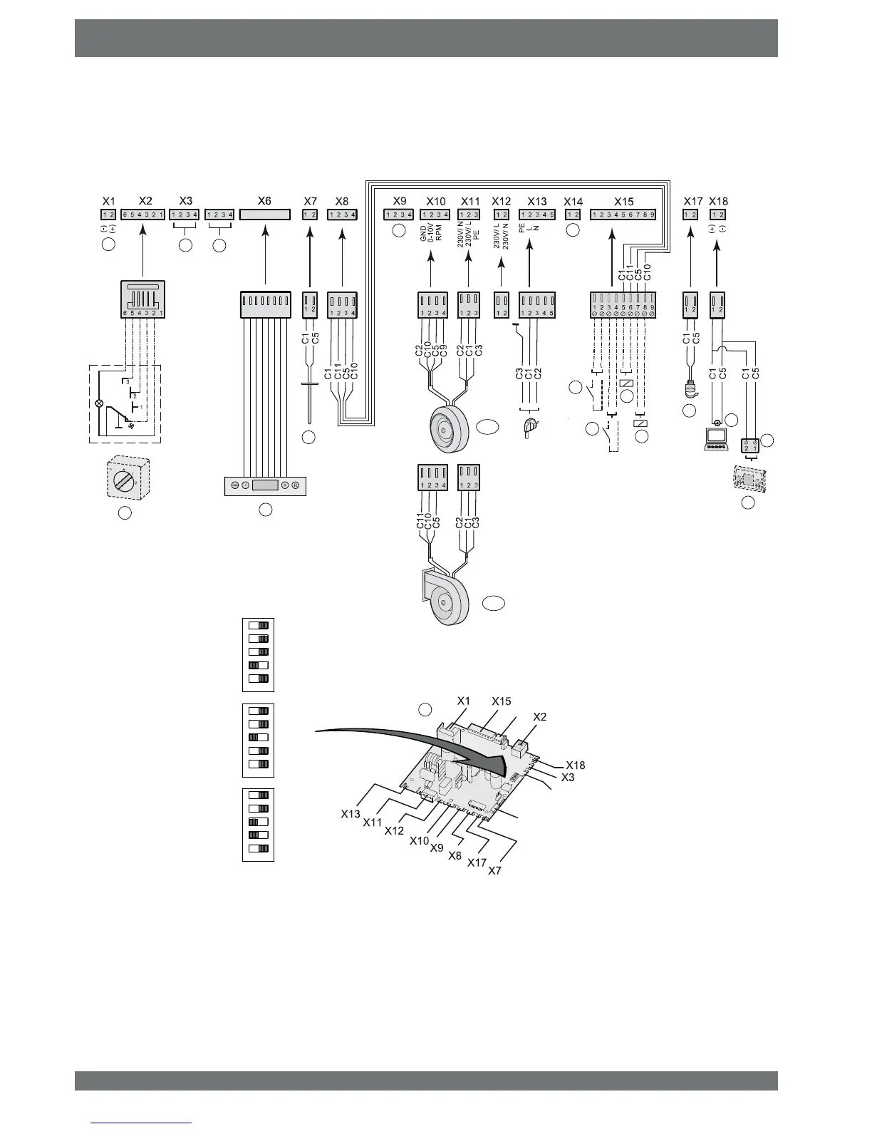
X4
X1
X6
4
&KDSWHU(OHFWULFGLDJUDPV
A = 0uOtipOe sZitcK
B = &ontroO 3aneO
C = Output temperature sensor (10K)
D1 = System fan (Oan 10 (Oan 16 2.0
D2 = System fan (Oan 25 2.1
( = SZitcK contact cooOing
) = SZitcK contact externaO fauOt
* = )rost safety reOay (24 9DC max 60 mA)
H = CooOing reOay (24 9DC mounted at (Oan ,nterface)
J =
Water temperature sensor (12K)
K = Service connector
L =
(Eus connector (poOarityspeci¿c)
0 = ControO unit (optionaO)
N = ControO pcE
3 =
Not appOicaEOe
10.1 Wiring diagram
X4
3
1 2 3 4 5 6 7 8
1 2 3 4 5 6 7 8
C1 = brown
C2 = blue
& JUHHQ\HOORZ
C5 = white
C9 = red
C10 = yellow
C11 = green
A
F
E
C
L
B
M
G
H
K
N
J
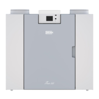
Elan 10 2.0
Elan 25 2.1
Elan 16 2.0
ON
ON
ON
P
P
P
P
P
'
'
 Loading...