Model 621 User’s Manual INITIAL INSTRUMENT SETUP
Bristol Instruments, Inc. 8
1 Verify that the line power meets the requirements shown below.
95 to 260 VAC
47 to 63 Hz
Protective Ground
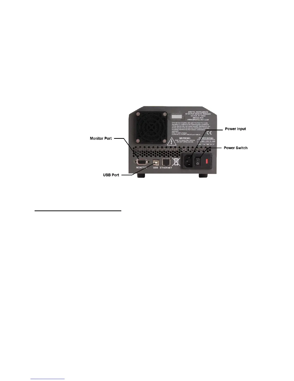
2 Connect the line-power cord to the power input connector on the instrument’s back
panel (Figure 2.1).
3 Connect the other end of the line-power cord to the power receptacle.
Figure 2.1: Back Panel
Signal Output Connections
The 621 Laser Wavelength Meter has the following connections for signal output and
communications. These connections are located on the instrument’s back panel
(Figure 2.1).
USB Port - Interface to a PC for instrument control and data reporting.
Ethernet Port – Not currently supported.
DB-9 Monitor Port - Used to monitor the interference fringe pattern and
instrument timing signals with an oscilloscope. A full description is provided in
Appendix D.
1 Connect the USB interface cable to the USB port on the back panel of the instrument.
2 Connect the other end of the USB cable to a USB port on your PC.