Model 621 User’s Manual LASER INPUT – IR AND MIR VERSIONS
Bristol Instruments, Inc. 13
4 LASER INPUT – IR AND MIR VERSIONS
Installation of Adjustment Feet
The IR and MIR versions of the 621 Laser Wavelength Meter are supplied with three
leg/feet assemblies (Figure 4.1) that are used to precisely align the instrument’s
Michelson interferometer to the laser under test.
1 Firmly attach the leg/feet assemblies to the 621 system by threading them onto the
three 10-32 x ¼ threaded studs emerging from the underside of the chassis.
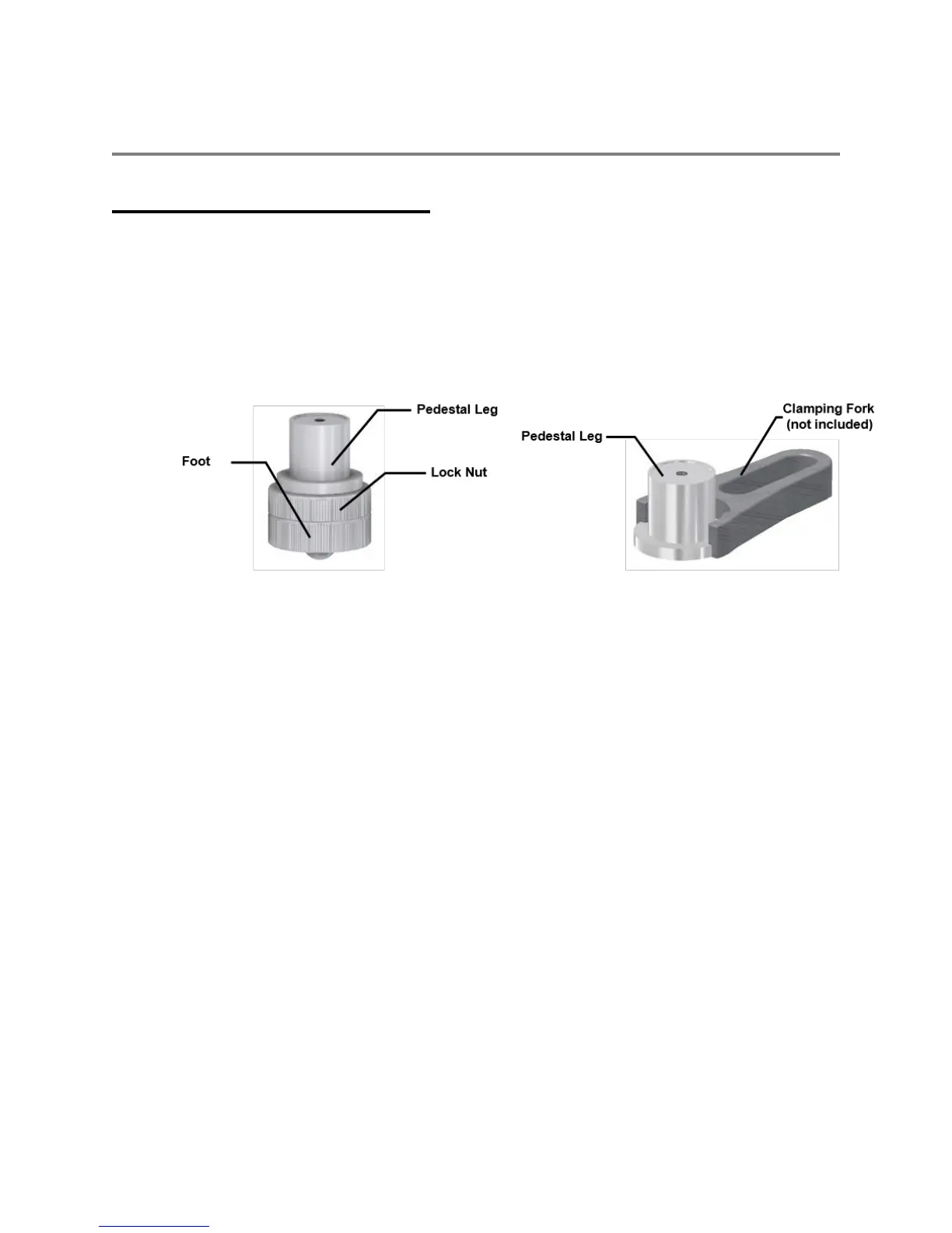
Figure 4.1: Model 621-IR/MIR Adjustment Feet
If desired, the 621 Laser Wavelength Meter can be securely attached to an optical table
using the Pedestal Legs and commonly available clamping forks.
1 Remove the Lock Nut and Foot components from each leg assembly.
2 Use three F1.0 Clamping Forks (not supplied) to secure each Pedestal Leg to the table.
3 Align the laser under test to the 621 system using two mirrors in a centering/pointing
configuration.