Broadcom 96xx User Guide
Broadcom
®
96xx PCIe 4.0, 24G SAS MegaRAID
™
and eHBA Tri-Mode Storage Adapters
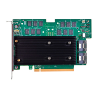
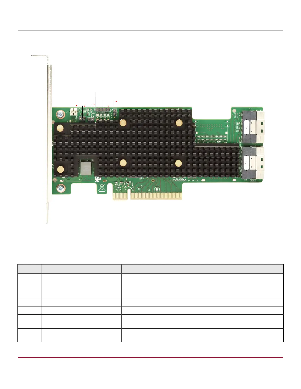
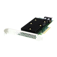
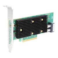
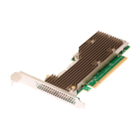
Figure 9: Card Layout for the eHBA 9620-16i Storage Adapter
J17
J18
J7
LED3
LED2
J11
J4
J10
J8
J2
The following table describes the headers and connectors on the adapter.
Table 27: Headers and Connectors
Connector Type Description
J2 Standard edge card connector The interface between the storage adapter and the host system.
With the PCIe interface, this connector provides power to the board and an
I
2
C interface connected to the I
2
C bus for the Intelligent Platform Management
Interface (IPMI).
J4 Default SBR header 2-pin connector. Reserved for Broadcom use.
J8 Onboard serial UART connector 4-pin connector. Reserved for Broadcom use.
J10 Global HDD activity LED header 2-pin connector.
Connects to an LED that indicates activity on the drives connected to the adapter.
J11 Global drive fault LED header 2-pin connector.
Connects to an LED that indicates whether a drive is in a fault condition.
Broadcom
96xx-MR-HBA-Tri-Mode-UG108
38