Broadcom 96xx User Guide
Broadcom
®
96xx PCIe 4.0, 24G SAS MegaRAID
™
and eHBA Tri-Mode Storage Adapters
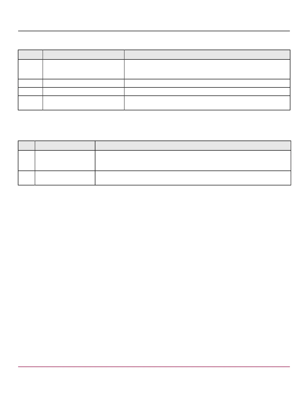
Table 31: Headers and Connectors
Connector Type Description
J2 Standard edge card connector The interface between the storage adapter and the host system.
With the PCIe interface, this connector provides power to the board and an I
2
C
interface connected to the I
2
C bus for the IPMI.
J4 Default SBR header 2-pin connector. Reserved for Broadcom use.
J8 Onboard serial UART connector 4-pin connector. Reserved for Broadcom use.
J17, J18 Storage interface connectors Two SFF-8654 8-port internal connectors.
Connect the adapter by cable to the storage devices.
The following table describes the LEDs on the adapter.
Table 32: LED Designations
LED Type Description
LED2 Yellow IOC overtemperature Stays on solid to indicate that the SAS4016 IOC temperature sensor is over the temperature
threshold. When the device is in the proper temperature range, this LED is off. This LED resides
on the nonheat-sink side of the board.
LED3 Green system heartbeat Indicates that the SAS4016 IOC is operating normally. This LED resides on the nonheat-sink
side of the board.
eHBA 9600-8i8e Adapter – Connector and LED Designations
The adapter is a 167.51 (±0.13) mm × 68.78 (±0.13) mm board. The component height on the top and bottom of the
adapter complies with the PCIe specification.
The following figure shows the connectors and LED locations on the adapter. A red circle near each header and connector
identifies pin 1 in the figure.
Broadcom
96xx-MR-HBA-Tri-Mode-UG108
42