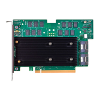
Broadcom 96xx User Guide
Broadcom
®
96xx PCIe 4.0, 24G SAS MegaRAID
™
and eHBA Tri-Mode Storage Adapters
Backplane Management
The SFF-8448 standard defines how to detect whether the backplane supports a SGPIO or two-wire interface (I
2
C) for
SAS/SATA usage. SFF-9402 is a superset of SFF-8448, adding the PCIe-defined sideband signal, which means that SAS/
SATA users see no change in backplane management detection when using the adapters.
Universal Backplane Management
The adapters provide LED operation and other backplane management of NVMe only, SAS/SATA only, or mixed-protocol
backplanes based on the SFF-TA-1005 specification. SFF-TA-1005 is an industry-standard backplane management
specification commonly known as Universal Backplane Management (UBM). As long as the backplane management
controller is designed in accordance with the UBM specification, the adapter automatically detects the backplane type and
functions appropriately.
The adapter supports the industry-standard SFF-TA-1005 Specification for Universal Backplane Management (UBM).
UBM provides the following key features:
•
Reports the backplane capabilities, including the following:
–
NVMe drive widths
–
Common REFCLK or separate REFCLK support
–
Maximum speeds
–
Designed slot power
•
Supports cable order independence, that is, the drive LED control and slot ID are not dependent on cable order.
•
Enables drive hot plug insertion through control of PERST# timing.
For existing SAS/SATA backplanes, if BP_TYPE = 0, the adapter uses SGPIO for legacy backplane management. Refer
to the SFF-8485 specification for functionality details. Design new backplanes with the industry-standard SFF-TA-1005
(UBM) specification for backplane management.
Virtual Pin Port Management
Broadcom requires new designs to enable UBM for backplane management. The adapter maintains support for Virtual Pin
Port (VPP) backplane management for legacy implementations. The adapters provide LED operation for NVMe devices
based on the VPP over I
2
C definition. Standard VPP implementation calls for one PCA9555 target per two devices. For
each drive pair, the adapter expects to see one PCA9555 target responding to address 0x4C on each pair of NVMe
drives.
Sideband Signals
The internal adapters have one or two x8 SFF-8654 connectors. Each x8 connector provides two sets of sidebands. This
section describes the sideband signal usage. The following table defines the sideband signal’s pins on the SFF-8654
connector. The last column in the table indicates the strength of the pull-up resistor or pull-down resistor values on the
adapter. See Table 13, Sideband Management Pin Settings, for the signal descriptions, and see Table 14, Internal x8
SFF-8654 Connector Pinout, for a complete connector pinout.
Broadcom
96xx-MR-HBA-Tri-Mode-UG108
17

 Loading...