Broadcom 96xx User Guide
Broadcom
®
96xx PCIe 4.0, 24G SAS MegaRAID
™
and eHBA Tri-Mode Storage Adapters
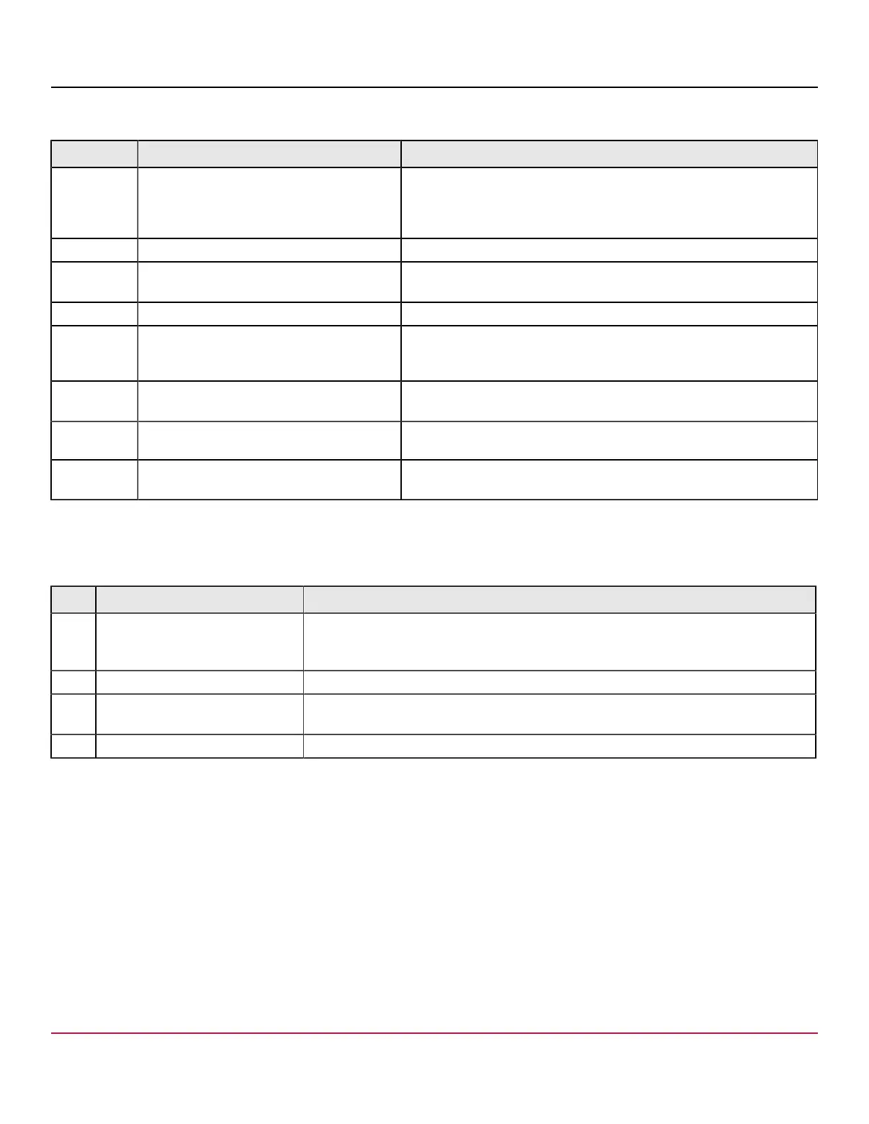
Table 20: Headers and Connectors
Connector Type Description
J2 Standard edge card connector The interface between the storage adapter and the host system.
With the PCIe interface, this connector provides power to the board and
an I
2
C interface connected to the I
2
C bus for the Intelligent Platform
Management Interface (IPMI).
J4 Default SBR header 2-pin connector. Reserved for Broadcom use.
J7 Advanced software options hardware key
header
2-pin connector.
Enables support for selected advanced features.
J8 Onboard serial UART connector 4-pin connector. Reserved for Broadcom use.
J10 Global HDD activity LED header 2-pin connector.
Connects to an LED that indicates activity on the drives connected to
the adapter.
J11 Global drive fault LED header 2-pin connector.
Connects to an LED that indicates whether a drive is in a fault condition.
J14 CacheVault power module interface
9-pin connector.
Connects the adapter to a CacheVault power module.
J17, J18 Storage interface connectors Two SFF-8654 8-port internal connectors.
Connect the adapter by cable to the storage devices.
The following table describes the LEDs on the adapter.
Table 21: LED Designations
LED Type Description
LED2 Yellow controller overtemperature Stays on solid to indicate that the SAS4116W RoC temperature sensor is over the
temperature threshold. When the device is in the proper temperature range, this LED is
off.
LED3 Green system heartbeat Indicates that the SAS4116W RoC ASIC is operating normally. This LED blinks at 1 Hz.
LED5 Yellow supercap fault Indicates that the CacheVault power module is in fault state or is overtemperature. When
the energy pack is in the FAULT condition or is missing, this LED is on.
LED6 Green ONFI activity Indicates when the ONFI is active for cache offload or recovery.
MegaRAID 9670-24i Adapter – Connector and LED Designations
The adapter is a 167.65 (±0.13) mm × 111.15 (±0.13) mm board. The component height on the top and bottom of the
adapter complies with the PCIe specification.
The following figure shows the connectors and LED locations on the adapter. Pin 1 on the headers and connectors is
highlighted in red in the figure.
Broadcom
96xx-MR-HBA-Tri-Mode-UG108
32