53-1003990-22 Installation Guide
Brocade
®
G620 Switch Hardware Installation Guide
–
52 bicolor (green/amber) LEDs to indicate the status for each port (one per SFP+ and one for each QSFP slot). (In
the G620 (Switch Type 183), the QSFP LEDs are tri-color.)
–
One green LED to indicate valid system power.
–
One bicolor (green/amber) LED to indicate the system status.
–
Two Ethernet LEDs: one green LED to indicate link speed of 1000/100/10Mb/s and one green LED to indicate
activity.
•
SEEPROM for switch identification.
•
Real-time power monitoring, voltage monitoring, and fan monitoring, including airflow direction.
•
Real-time digital thermometers for temperature monitoring.
•
Real-time clock (RTC) with battery.
License Options
The Brocade G620 Switch uses a capacity-based Ports on Demand (POD) license method. An Integrated Routing (IR)
license is required to enable EX_Ports on this device. Refer to the Brocade Fabric OS Software Licensing Guide for more
details.
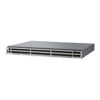
Port-Side View of the Device
The following illustration shows the port-side view of the Brocade G620 (Switch Type 162) Fibre Channel switch.
Figure 1: Port-Side View of G620 (Switch Type 162)
1. System Status LED
2. System Status LED
3. UART RJ-45 Serial Console Port
4. SFP+ FC (four upper and four lower) Ports 0–7
5. SFP+ FC (four upper and four lower) Ports 8–15
6. SFP+ FC (four upper and four lower) Ports 16–23
7. SFP+ FC (four upper and four lower) Ports 24–31
8. SFP+ FC (four upper and four lower) Ports 32–39
9. SFP+ FC (four upper and four lower) Ports 40–47
10. QSFP Port 0 (FC Ports 48–51)
11. QSFP Port 2 (FC Ports 56–59)
12. QSFP Port 3 (FC Ports 60–63)
13. QSFP Port 1 (FC Ports 52–55)
53-1003990-22
10