53-1003990-22 Installation Guide
Brocade
®
G620 Switch Hardware Installation Guide
Monitoring the Device
The power-on self-test (POST) performs diagnostic tests every time the device is powered on, rebooted, or reset. The
LEDs on the device indicate system activity and status.
Interpreting Port-Side LEDs
System activity and status can be determined through the activity of the LEDs on the switch.
•
48 bicolor (green/amber) port status LEDs, one for each SFP+ port.
•
4 tri-color LEDs, one for each QSFP port on the switch. The QSFP LED flashes 1 to 4 times to indicate whether the
focus is on port 0 (1 flash), port 1 (2 flashes), port 2 (3 flashes), or port 3 (4 flashes).
The LEDs have three possible states: no light, a steady light, and a flashing light. Flashing lights may be slow, fast, or
flickering. The lights are green or amber.
Sometimes, the LEDs may flash any of the colors during boot, POST, or other diagnostic tests. This flashing is normal;
it indicates a problem only if the LEDs indicate an unhealthy state after all boot processes and diagnostic tests are
complete.
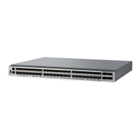
Figure 34: Brocade G620 Port-Side LEDs (Switch Type 162)
1. System Status LED
2. System Power LED
3. SFP+ (Upper) Port 0 Status LED
4. SFP+ (Lower) Port 4 Status LED
5. FC Port 52 (QSFP 1) Status LED
6. FC Port 53 (QSFP 1) Status LED
7. FC Port 54 (QSFP 1) Status LED
8. FC Port 55 (QSFP 1) Status LED
9. FC Port 60 (QSFP 3) Status LED
10. FC Port 61 (QSFP 3) Status LED
53-1003990-22
60