6 Brocade FastIron WS Hardware Installation Guide
53-1002188-01
Hardware features
1
DRAFT: BROCADE CONFIDENTIAL
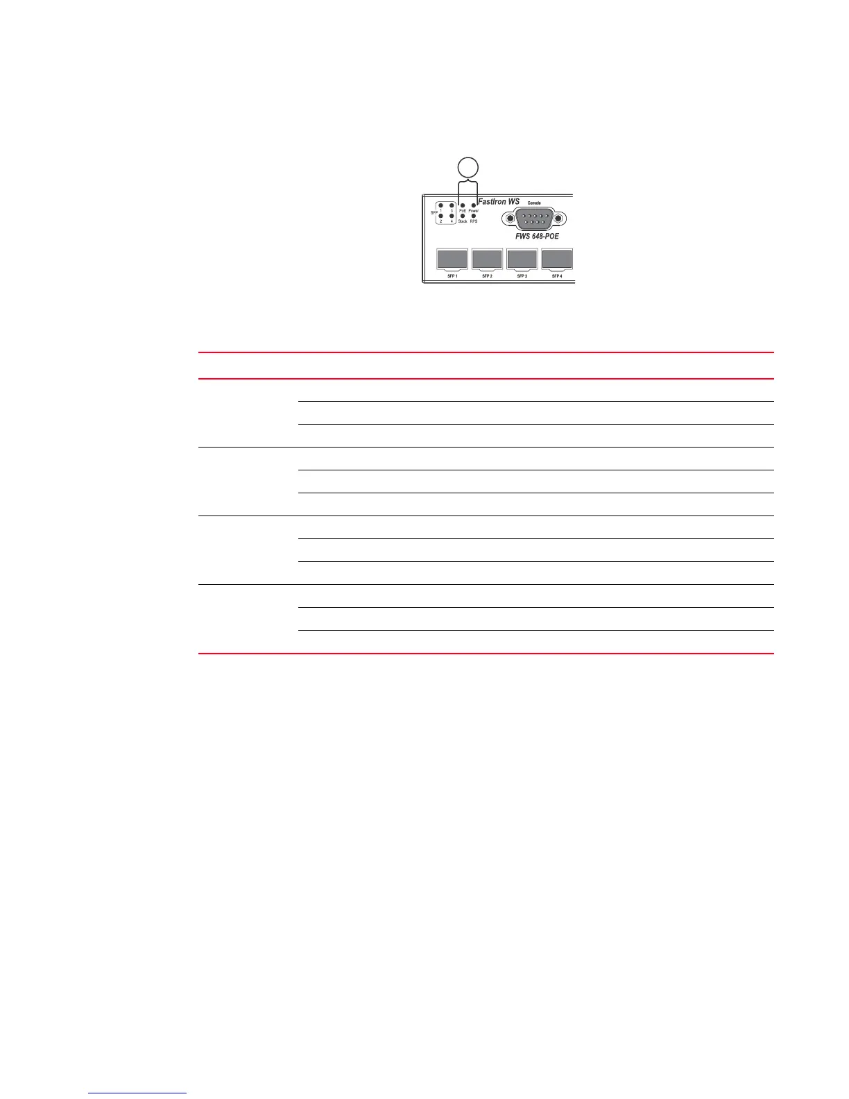
FIGURE 8 System status LEDs
Power supplies
Optional redundant power supply
FWS devices support an optional redundant power supply (RPS), that can provide power to the
switch in the event the internal power supply fails.
Power supply receptacles
There are two power receptacles on the rear panel of each switch. The standard power receptacle
is for the AC power cord. The receptacle labeled “RPS” is for the optional redundant power supply
cord.
2System status LEDs
TABLE 3 System status LEDs
LED Condition Status
Power Green Internal power is operating normally.
Amber Internal power supply fault.
Off Power off or failure.
Stack Off System stand alone
Green System in stacking master mode
Amber System in stacking slave mode
RPS Green Redundant power supply is providing power.
Amber Primary power supply is active, RPS is on standby.
Off Redundant power supply is off or not plugged in.
POE Green POE module is operating normally.
Amber POE module fault.
Off POE module not present.
 Loading...