EasyManuals Logo

Brocade Communications Systems FWS624 User Manual

Brocade Communications Systems FWS624
74 pages
To Next Page IconTo Next Page
To Previous Page IconTo Previous Page
Page #34 background imageLoading...
Page #34 background image
24 Brocade FastIron WS Hardware Installation Guide
53-1002188-01
Installing a redundant power supply
2
DRAFT: BROCADE CONFIDENTIAL
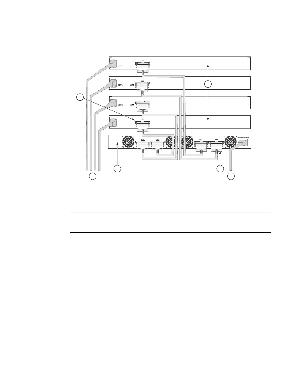
FIGURE 22 Connecting multiple devices to a redundant power supply.
NOTE
For International use, you may need to change the AC line cord. You must use a line cord set that
has been approved for the receptacle type in your country.
Port pin-out diagram for the RPS2-EIF power supply
Figure 23 and Table 9 describe the pin-outs for the RPS2-EIF power supply.
1Input port 4 FWS devices
2 AC power supply no.1 5 Output port
3 Redundant power supply 6 AC power supply no.2
1
5
3
6
4
2

Table of Contents

Questions and Answers:

Question and Answer IconNeed help?

Do you have a question about the Brocade Communications Systems FWS624 and is the answer not in the manual?

Brocade Communications Systems FWS624 Specifications

General IconGeneral
BrandBrocade Communications Systems
ModelFWS624
CategorySwitch
LanguageEnglish

Related product manuals