50 Brocade FastIron WS Hardware Installation Guide
53-1002188-01
Hardware specifications for FastIron WS models
5
DRAFT: BROCADE CONFIDENTIAL
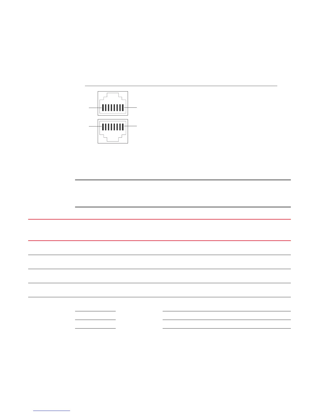
FIGURE 31 Pin assignment and signalling for 10/100BaseTX and 1000BaseT ports
Cable specifications
Table 20 lists the cable specifications for the cables used with the 10/100 Ethernet ports.
Cable installation and network configuration will affect overall transmission capability. The numbers
provided below represent the accepted recommendations of the various standards. For
network-specific recommendations, consult your local Brocade reseller or system engineer.
Pin Number
1
2
3
4
5
6
7
8
1
2
3
4
5
6
7
8
8
1
1
8
RD+
RD-
TD+
Not used
TD-
Not used
Not used
Not used
RD+
RD-
TD+
CMT
TD-
CMT
CMT
CMT
Pin Assignment MDI-X ports MDI-X ports
10BaseT
Pin Number
100BaseTX and 1000BaseT
TABLE 20 Cable length summary table
Cable type Connector type Core diameter
(microns)
Modal bandwidth
(MHz*km) or
wavelength (nm)
Range (meters)
1000Base-BX-D Single-mode Fiber
(SMF)
LC connector for SFP
module
9 1490 nm 2 – 10000 (10km)
1000Base-BX-U SMF LC connector for SFP
module
9 1310 nm 2 – 10000 (10km)
1000Base-LHA SMF LC connector for SFP
module
9 1550 nm 2 – 70000 (70km)
1000Base-LHB SMF LC connector for SFP
module
9 1550 nm 2 – 120000 (120km)
1000Base-LX Multi-mode Fiber
(MMF)
LC connector for SFP
module
62.5 500 2 – 550
MMF 50 400 2 – 550
MMF 50 500 2 – 550
SMF 9 1300 nm 2 – 10000
 Loading...