Brocade FastIron WS Hardware Installation Guide 23
53-1002188-01
Installing a redundant power supply
2
DRAFT: BROCADE CONFIDENTIAL
Connecting devices to the redundant power supply
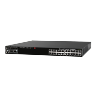
The FastIron RPS2-EIF is supported on the following devices:
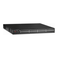
• FastIron WS624
• FastIron WS648
The FastIron RPS12 is supported on the following devices:
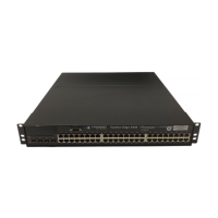
• FastIron FWS624-POE
• FastIron FWS648-POE
To connect devices to a redundant power supply, follow these steps.
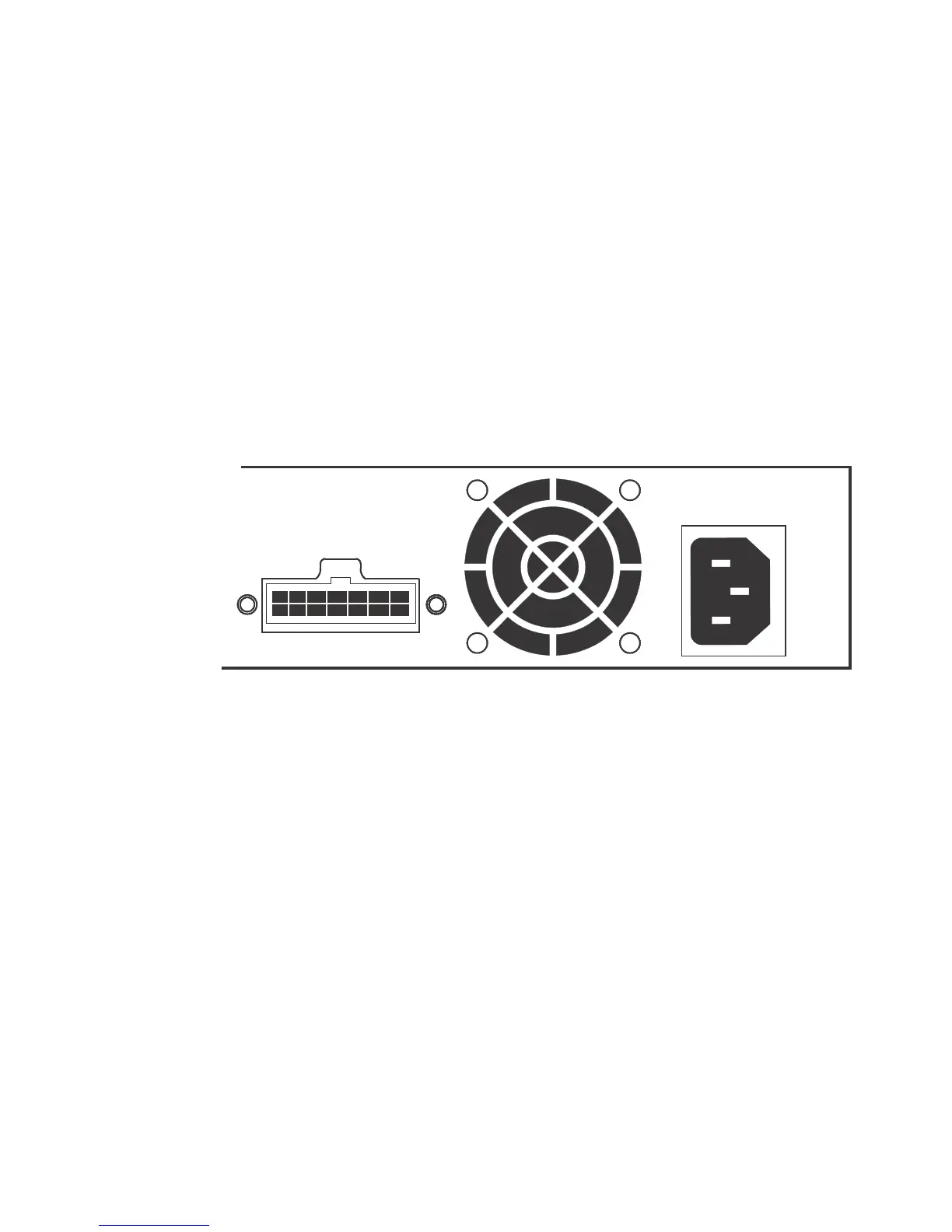
1. Connect one end of the AC cord to the AC receptacle on the device, and the other end to a
grounded power outlet. Refer to Figure 21.
FIGURE 21 Power receptacle
2. Connect one end of a DC cord to the redundant power receptacle on the device and the other
end to an available receptacle on the redundant power supply.
3. Repeat step 1 and step 2 to connect up to four devices to the redundant power supply. Refer to
Figure 22.
4. Connect one end of the AC cord to the AC receptacle on the redundant power supply, and the
other end to a grounded power outlet.
5. Check the LEDs on the redundant power supply to ensure proper operation. On the RPS2-EIF
and RPS12, the Power LED should light up. If the LEDs do not light, refer to “Troubleshooting”
on page 53 for more information.
100-240V, 50-60Hz 10A
RPS 1