Brocade FastIron WS Hardware Installation Guide 25
53-1002188-01
Installing a redundant power supply
2
DRAFT: BROCADE CONFIDENTIAL
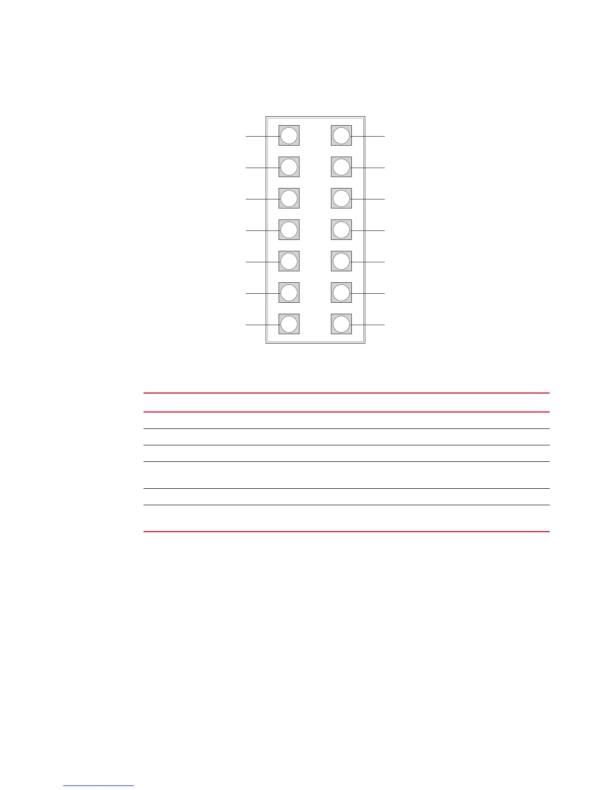
FIGURE 23 RPS2-EIF power supply port pinout diagram
Port pin-out diagram for the RPS12 power supply
Figure 24 and Table 10 describe the pin-out diagram for the RPS12 power supply.
TABLE 9 Port pin-out diagram for the RPS2-EIF power supply
Pin Name Description
1, 7, 8, 14 GND Ground connection
2, 9 N.C. No current
3, 4, 5, 6 12 V 12 volts current
10 RPS Present Indicates that a redundant power supply is attached and
functioning
11, 12 Status 1, Status 2 Status indicator
13 Power Good Indicates that power is being supplied to the redundant
power supply
N.C.
N.C.
GND
12 V RPS Present
12 V Status 1
12 V Status 2
12 V Power Good
GND GND