Brocade FastIron WS Hardware Installation Guide 19
53-1002188-01
Installing a redundant power supply
2
DRAFT: BROCADE CONFIDENTIAL
Package contents
• Redundant power supply (RPS12)
• One AC supply power cord — US, Continental Europe or UK
• One DC power cord with IEC connectors on both ends (length 152 cm each)
• Rack Mounting Kit containing brackets and screws
• Adhesive feet
• User agreement envelope
• Registration card
LEDs
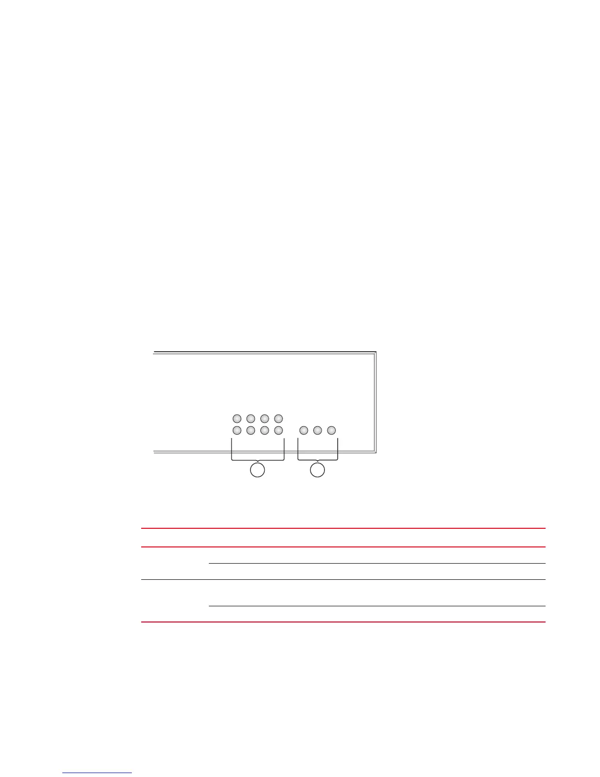
Figure 17, Table 6, and Table 7 describe the functions of the RPS12 LEDs.
FIGURE 17 FastIron RPS12 LEDs
1 Power socket 2 Redundant power sockets 4-3
3 Redundant power sockets 2-1 4 Power system status indicator
1 Port indicators 2 System indicators
TABLE 7 Port Status LEDs - RPS12
LED (1~4) Condition Status
Link Off The port does not have a valid connection to a device.
On Yellow The port has a valid connection to a device
Activity Off The port may be connected to a device, but is not delivering power to
the device.
On Green The port is providing power to a connected device.
Status
P
ower
Fa
n
Activity
Link
1234
21
 Loading...