28 Brocade FastIron WS Hardware Installation Guide
53-1002188-01
Attaching a PC or terminal
2
DRAFT: BROCADE CONFIDENTIAL
1. Connect a PC or terminal to the serial port using a straight-through cable. The serial port has a
male DB-9 connector.
You will need to run a terminal emulation program on the PC.
2. Open the terminal emulation program and set the session parameters as follows:
• Baud: 9600 bps
• Data bits: 8
• Parity: None
• Stop bits: 1
• Flow control: None
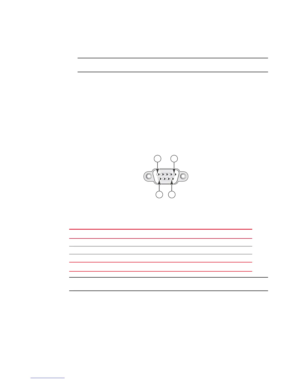
The serial communication port acts as a management connection point for a PC or SNMP
workstation. Brocade devices have a standard male DB-9 connector, shown in Figure 25.
FIGURE 25 Serial port (DB-9 DTE) pin-out
Most PC serial ports also require a cable with a female DB-9 connector. Terminal connections will
vary, requiring either a DB-9 or DB-25 connector, male or female. Serial cable options between a
Brocade device and a PC or terminal are shown in Table 11.
As indicated in Table 11, some of the wires should not be connected.
TABLE 11 Serial cable wiring map
9-pin serial port on device Null modem 9-pin DTE port on PC
2 TXD (transmit data) ----------------------------> 2 RXD (receive data)
3 RXD (receive data) <---------------------------- 3 TXD (transmit data)
5 SGND (signal ground) <--------------------------> 5 SGND (signal ground)
No other pins are used.
 Loading...