3-25
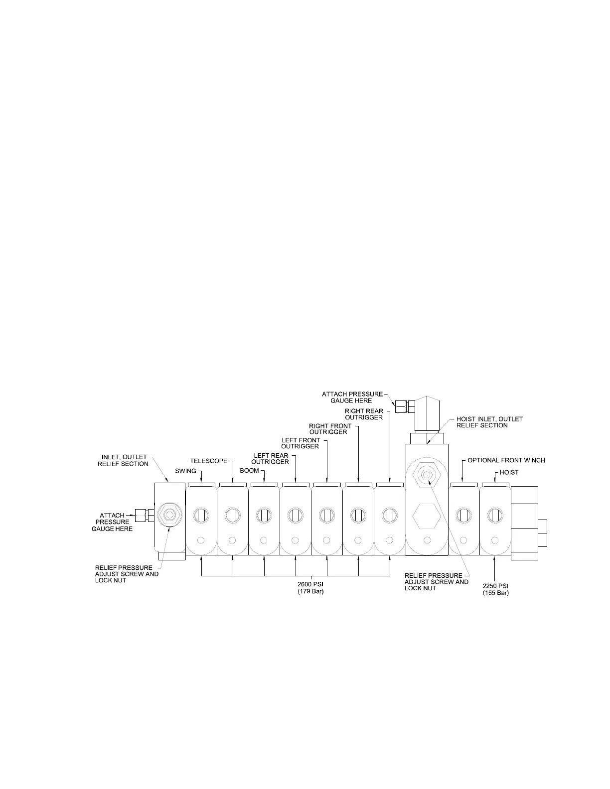
CONTROL VALVE ADJUSTMENTS
The crane control valve has two relief valves to protect the hydraulic components. The
relief valves are adjustable and should be checked and set as follows:
1. Boom and outrigger circuits -- 2600 PSI (179 bar) at full flow.
2. Hoist circuit -- 2250 PSI (155 bar) at full flow.
BOOM AND OUTRIGGER CIRCUITS:
Remove the 3/8-inch tube cap from the test fitting on the left-hand side of the control
valve and install a 3000 PSI (200 bar) test gauge. To obtain full flow reading, run pump
at full speed and actuate BOOM control lever to LOWER position, and hold until
maximum reading is made. If a pressure of 2600 PSI (179 bar) is not possible, check the
following:
1. Low oil level in the reservoir.
2. Clogged suction filter or shut-off valve not fully opened.
3. Valve spool linkage not allowing control valve to fully open. Valve spool should
move 5/16 of an inch (8 mm) each way from neutral.
4. Adjust relief valve by removing cap on end of relief cartridge, and turning socket
head screw clockwise to increase pressure, or counter-clockwise to lower
pressure.
5. Foreign particle in pilot-operated relief.
6. Broken mechanical connection to the pump shaft.
7. Worn or defective hydraulic pump.
HOIST CIRCUIT:
The relief pressure for the hoist valve can be adjusted similarly to the boom circuit.
Connect a 3000 PSI (200 bar) gauge to the test fitting on the mid-inlet section of the
valve. Disconnect both hoses at hoist motor and install plugs. Do not connect hoses
together. Operate hoist control in either direction. Run engine at full throttle. Adjust
relief valve to 2250 PSI (155 bar) at full flow.