Brookeld Engineering Laboratories, Inc. Page 16 Manual No. M14-023
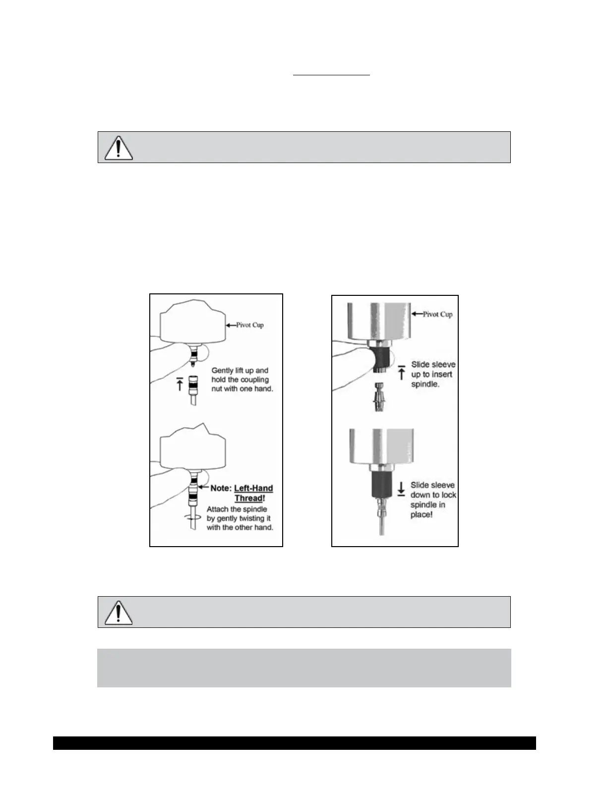
e spindles are attached to the viscometer by screwing them onto the coupling nut on the lower sha
(see Figure II-3). Note that the spindles have a le-hand thread. e lower sha should be secured
and slightly lied with one hand while screwing the spindle to the le. e face of the spindle nut
and the matching surface on the lower sha should be smooth and clean to prevent eccentric rotation
of the spindle. Spindles can be identied by the number on the side of the spindle coupling nut.
e motor should be OFF whenever spindles are being removed or attached.
If your instrument has the EZ-Lock system, the spindles are attached as follows:
With one hand, hold the spindle, while gently raising the spring-loaded outer sleeve to its highest
position with the other hand, as shown in Figure II-4. Insert the EZ-Lock Spindle Coupling so that
the bottom of the coupling is ush with the bottom of the sha, and lower the sleeve. e sleeve
should easily slide back down to hold the spindle/coupling assembly in place for use. [Spindles
can be identied by entry code; look for the number on the side of the EZ-Lock spindle coupling.]
Figure II-3
Figure II-4
e motor should be OFF whenever spindles are being removed or attached.
NOTE: Keep the EZ-Lock Spindle Coupling and outer sleeve as clean as possible
and free from debris that could become lodged inside the adapter.