Brookeld Engineering Laboratories, Inc. Page 5 Manual No. M14-023
I. INTRODUCTION
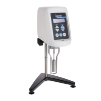
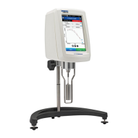
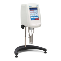
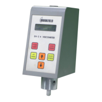
e Brookeld DV1 Viscometer series has provided exceptional value for viscometer users since its
introduction in 1981. Brookeld has continued to develop and improve the DV1 to maintain its position
in the market as the best value for Q/C applications. e Brookeld DV1 Viscometer continues in this
tradition of innovation, quality and value. e incorporation of a large graphical display and “Hot Keys”
has allowed for a new and improved user interface that preserves single speed data collection methods
(or multiple speeds when using Wingather SQ), which makes using the DV1 Viscometer easier than
ever before.
e Brookeld DV1 Viscometer measures uid viscosity which is a measure of a uid’s resistance to
ow. You will nd a detailed description of the science of viscosity in the Brookeld publication “More
Solutions to Sticky Problems”, a copy of which was included with your DV1.
e principle of operation of the DV1 is to drive a spindle (which is immersed in the test uid) through
a calibrated spring. e viscous drag of the uid against the spindle is measured by the spring deection.
Spring deection is measured with a rotary transducer. is system provides continuous sensing and
display of the measurement during the entire test. e measurement range of a DV1 (in centipoise
or milliPascal-seconds) is determined by the rotational speed of the spindle, the size and shape of the
spindle, the container the spindle is rotating in, and the full-scale torque of the calibrated spring.
ere are four basic spring torque series oered by Brookeld:
Spring Torque
Model dyne•cm milli Newton•m
DV1MLV 673.7 0.0673
DV1MRV 7,187.0 0.7187
DV1MHA 14,374.0 1.4374
DV1MHB 57,496.0 5.7496
e higher the torque calibration, the higher the measurement range. e viscosity measurement range
for each torque calibration may be found in Appendix B.
e DV1 is congured to accept an optional temperature probe, which allows temperature readout over
the range -100°C to +300°C (-148°F to + 572°F). is option allows ambient temperature measurement
or temperature measurement of the sample during viscosity testing. Contact Brookeld or your local
Brookeld dealer for more information on this instrument option.
All units of measurement are displayed according to either the CGS system or the SI system.
1. Viscosity appears in units of centipoise (shown as “cP”) or milliPascal-seconds (shown as
mPa•s) on the DV1 Viscometer display.
2. Torque appears in units of dyne-centimeters or Newton-meters (shown as percent “%”)
in both cases) on the DV1 Viscometer display.
3. Temperature appears in units of Celsius (shown as C) or Fahrenheit (shown as F) on the
DV1 Viscometer display.
e following applies to DV1 Viscometers when using an optional temperature probe. Look for the
symbol
throughout this manual for instructions pertaining specically to DV1 Viscometers with
temperature probe option.
 Loading...
