Brookeld Engineering Laboratories, Inc. Page 31 Manual No. M14-023
Appendix A - Cone/Plate Viscometer Set-Up
is Cone/Plate version of the DV1 uses the same operating instruction procedures as described in
this manual. However, the “gap” between the cone and the plate must be veried/adjusted before
measurements are made. is is done by moving the plate (built into the sample cup) up towards the
cone until the pin in the center of the cone touches the surface of the plate, and then by separating
(lowering) the plate 0.0005 inch (0.013mm).
When operating the Cone/Plate at elevated temperature, the gap must be set with the cup and
spindle equilibrated at the temperature recommended. Maximum temperature for Cone/Plate
operation is 80°C. Maximum operational temperature of sample cup is 100
°C. Personal protection
is recommended when controlling to temperatures above 80°C.
Note: Micrometer Adjustment Ring will become hot when controlling sample
cup at temperatures above 50°C.
DV1 Cone/Plate Viscometers have an Electronic Gap Setting feature. is feature enables the user
to easily nd the 0.0005 inch gap setting that was established at Brookeld prior to shipment.
Brookeld recommends that the maximum particle size in the sample material for measurement
with cone/plate geometry be less than 5 times the gap setting. A more conservative approach is to
limit the maximum particle size to less than 10 times the gap setting.
e following information explains how to set the Electronic Gap and verify calibration of the DV1
Viscometer.
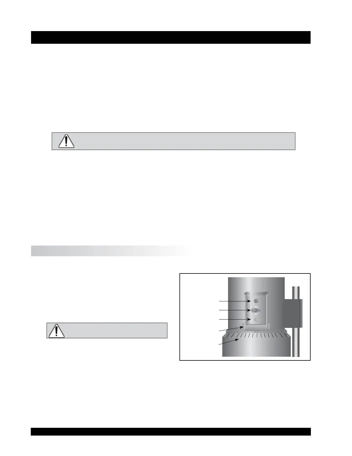
A.1 Electronic Gap Setting Features
TOGGLE SWITCH allows you to enable/disable the
Electronic Gap Setting Feature: le position is
OFF (disabled), right position is ON (enabled).
PILOT LIGHT is the red (LED) light; when
illuminated, it means the Electronic Setting
Function is sensing (enabled).
Note: Be sure the light is o before
introducing the test sample.
CONTACT LIGHT is the yellow (LED) light; when
it rst turns on, the “hit point” has been found.
SLIDING REFERENCE MARKER is used aer nding
the “hit point;” it is the reference for establishing
the 0.0005 inch gap.
MICROMETER ADJUSTMENT RING is used to move the cup up or down in relation to the cone spindle.
Turning the ring le (clockwise) lowers the cup; turning it right (counterclockwise) raises the cup.
Each line on the ring represents one scale division and is equivalent to 0.0005 inch movement of
the plate relative to the cone.
Figure A-1
Pilot Light
(red)
Toggle Swtich
Contact Light
(yellow)
Sliding Reference
Marker
Micrometer
Adjustment Ring