Brookeld Engineering Laboratories, Inc. Page 32 Manual No. M14-023
A.2 Setup
1. Be sure that the Viscometer is securely mounted
to the Laboratory Stand, leveled and zeroed
with no cone or cup attached and 0% torque
is displayed.
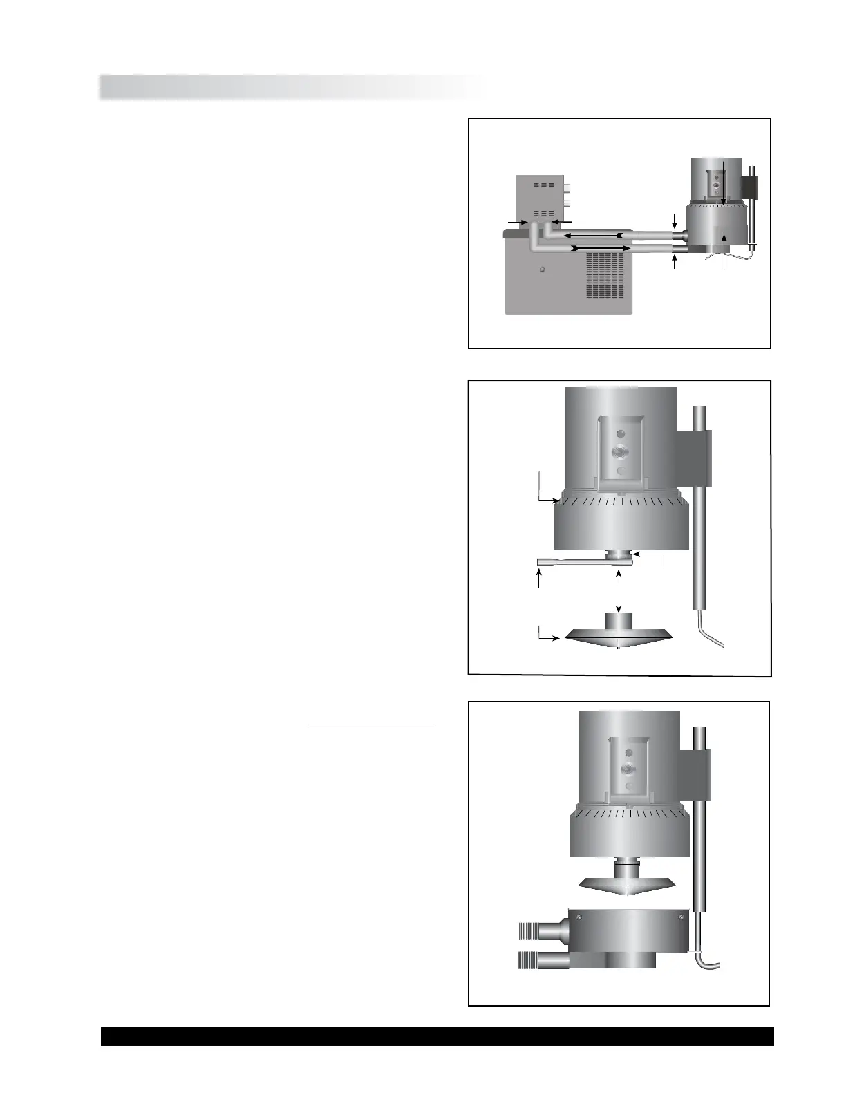
2. Figure A-2 shows a typical water bath setup.
Connect the sample cup inlet/outlet ports
to the water bath inlet and outlet and set the
bath to the desired test temperature. Allow
sucient time for the bath to reach the test
temperature. e temperature range of the
Sample Cup (CPE-44Y or CPE-44PY) is 0°-
100°C. Brookeld recommends a maximum
temperature of 80°C to allow for direct hand
contact for adjustment of the micrometer ring.
When using the sample cup at temperatures
near 0°C, be careful to avoid frost buildup on
the top surface of the cup; this could prevent a
proper t with the micrometer ring. Please refer
to the bath manual for the proper selection of
bath uid and tubing to ensure safe and proper
operation.
3. e Viscometer has been supplied with a special
cone spindle(s), which contains the Electronic
Gap Setting feature. e “CPE” part number
designation on the cone veries the Electronic
Gap Setting feature.
4. With the motor o, thread the cone spindle
by using the spindle wrench to secure the
viscometer coupling nut (see Figure A-3);
gently push up on the coupling nut and hold
this securely with the wrench. read the cone
spindle by hand. Note: Le Hand reads.
5. Attach the cup, taking care not to hit the cone
with the cup (Figure A-4). ere must be no
uid in the cup.
6. Option: e sample cup is available with an
optional purge tting. e user can connect
a dry gas line to this and put a blanket of dry
gas over the sample during measurement, if
desired.
Figure A-3
Spindle
Wrench
(CPE) Cone
ese surfaces
must be clean!
Coupling Nut
Micrometer
Adjustment
Ring
Do Not hit the
CONE with the CUP!
Figure A-4
Sample
Cup
(CPE-44Y
or
CPE-44PY)
Bath/Circulator
Bath
Inlet
Bath
Outlet
Cup
Outlet
Cup
Inlet
Micrometer
Ring
Figure A-2