Brookeld Engineering Laboratories, Inc. Page 33 Manual No. M14-023
A.3 Setting the Gap
1.
Move the toggle switch to the right; this will
turn on (enable) the Gap Setting Feature. e
Pilot (red) light will be illuminated.
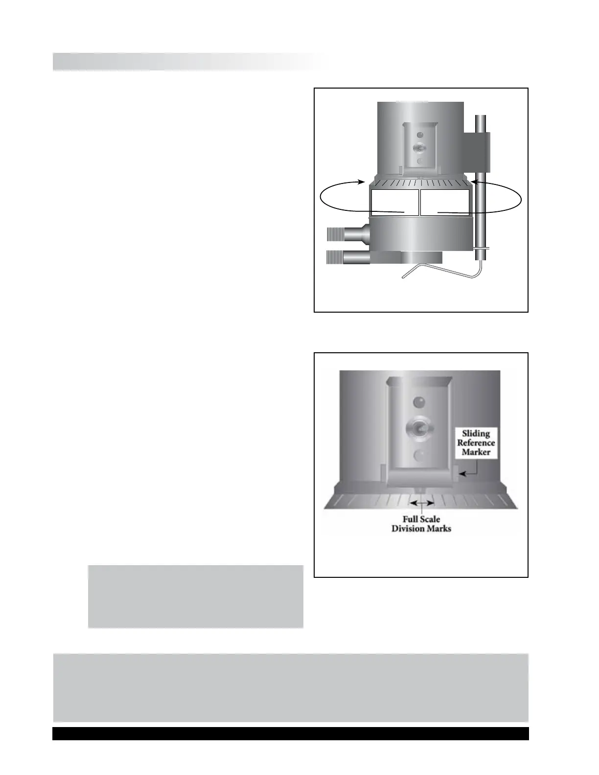
2. If the contact light (yellow) is illuminated, turn
the micrometer adjustment ring clockwise (as
you look down on the instrument) until the
light is just breaking contact, i.e., ickering
(see Figure A-5).
3. If the yellow contact light is not illuminated,
slowly turn the micrometer adjustment ring in
small increments (one or two scale divisions)
counter-clockwise.
Continue moving the micrometer adjustment ring slowly
counter-clockwise until the contact light
(yellow) turns on. Back o (rotate clockwise)
until the light is just breaking contact, i.e.,
ickering.
4. Adjust the sliding reference marker, right or
le, to the closest full scale division mark (see
Figure A-6).
5. Turn the micrometer adjustment ring one
scale division to the le to meet the line on
the sliding reference marker. THE YELLOW
CONTACT LIGHT SHOULD GO OFF.
6. You have established the gap space needed for
measurement. NOW TURN THE TOGGLE
SWITCH OFF (LEFT); THE RED PILOT
LIGHT SHOULD GO OFF.
7. Carefully remove the sample cup.
LEFTx
Moves Towards
Hit Point
(counter-clockwise)
RIGHT
Moves Away
from Hit Point
(clockwise)
Figure A-5
Figure A-6
is viscosity of “electrically conductive”
uids may be aected if readings are taken
with the Electronic Gap Setting feature “on”.
Be sure to shut the feature “o ” before taken
readings!
Notes:
1. e cup may be removed and replaced without resetting the gap, if the micrometer
adjustment ring has not been moved.
2. Remove the spindle from the viscometer when cleaning.
3. Re-establish the hit point every time the spindle is attached/detached.