Brookeld Engineering Laboratories, Inc. Page 51 Manual No. M14-023
Calibration Check Procedures for DIN Adapter
When a DIN UL Adapter is used, the water bath is stabilized at the proper temperature:
1) Put the proper amount of viscosity standard uid into the UL Tube. (Refer to the UL
Adapter instruction manual).
2) Attach the spindle (with extension link and coupling nut) onto the DV1.
3) Attach the tube to the mounting channel.
4) Lower the tube into the water bath reservoir, or if using the ULA-40Y water jacket, connect
the inlet/outlets to the bath external circulating pump.
5) Allow sucient time for the viscosity standard, sample chamber and spindle to reach test
temperature.
6) Measure the viscosity and record the viscometer reading; include % and cP (mPa•s).
NOTE: e spindle must rotate at least ve (5) times before readings are taken.
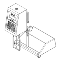
Calibration Check Procedure for a Helipath Stand and T-Bar Spindles
T-Bar spindles should not be used for verifying calibration of the DV1 Viscometer.
When a Helipath Stand and T-Bar spindles are used:
Remove the T-bar spindle and select a standard LV (#1-3) or RV,HA,HB (#1-6) spindle.
Follow the procedures in the beginning of this section, entitled Calibration Procedure for
LV (#1-3) and RV, HA, HB (#1-6) Brookeld spindles.
Calibration Check Procedure for Spiral Adapter
1) Place the viscosity standard uid (in the proper container) into the water bath.
2) Attach the spindle to the viscometer. Attach chamber (SA-1Y) and clamp to the viscometer.
3) Lower the DV1 into measurement position. Operate the viscometer at 50 or 60 RPM until
the chamber is fully ooded.
4) e viscosity standard uid, together with the spindle, should be immersed in the bath.
Don’t introduce air bubbles.
Stirring the uid periodically (operate at 50 or 60 RPM), prior to taking measurements to
encourage temperature equilibrium.
NOTE: e spindle must rotate at least ve (5) times before readings are taken.
 Loading...
