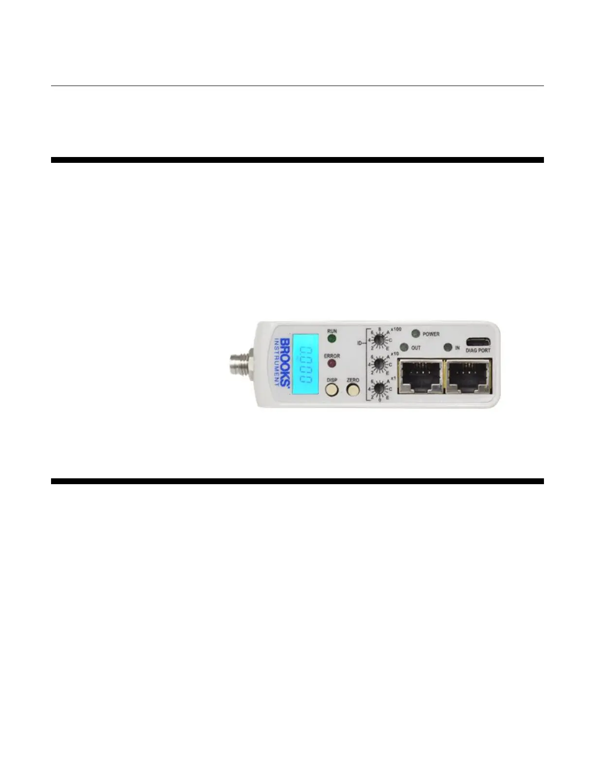
2.2. Physical Interfaces
The available physical interfaces on the EtherCAT device are listed below.
Refer to the GF100 Series Installation and Operation Manual for more
details.
Integrated LCD display
Display push button- cycle through information and rotate display
Zero push button- easily re-zero the device
Micro-USB Diagnostic Port
Twin RJ45 external top mounted communication connections
5-pin M8 threaded male connector for power located on upper inlet side
2.2.1. Power Supply
Power needs to be supplied via the standard male M8 5-pin connector. The
M8 connector is located on the upper inlet side of the device. Refer to
Figures 2-2 and 2-3 below.