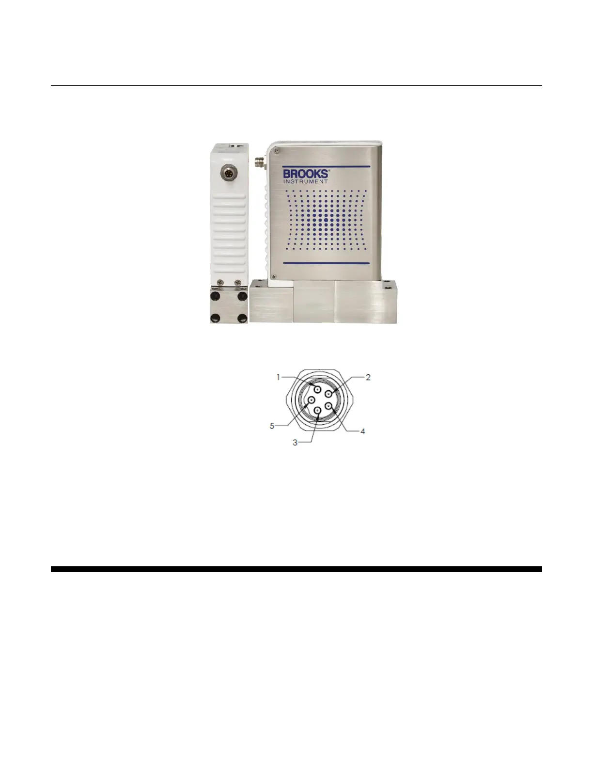
EasyManua.ls Logo

Brooks GF125 - Leds; Figure 2-2 - M8 Power Connector Location; Figure 2-3 - M8 Power Connector Drawing

Default Icon
54 pages
Print Icon
To Next Page IconTo Next Page
To Previous Page IconTo Previous Page
Loading...
Installation and Operation Manual
X-DPT-EtherCAT-GF1XX-MFC-eng
Part Number: 541B219AAG
April, 2017
13
Section 2 - Quick Start
Brooks EtherCAT MFCs
Figure 2-2 M8 Power Connector Location
Figure 2-3 M8 Power Connector Drawing
Pin 1: +24V
Pin 3: Power Common
2.2.2. LEDs
The POWER LED indicates that the device is supplied sufficiently with
power.
The IN and OUT port LEDs indicate whether the respective removable port is
connected.
The RUN indicator shows the status of the EtherCAT State Machine. Refer to
Table 2-1 below for indicator states and descriptions.

Table of Contents

Related product manuals