~
Replacing
circuit
boards
Suppo:---n
P13
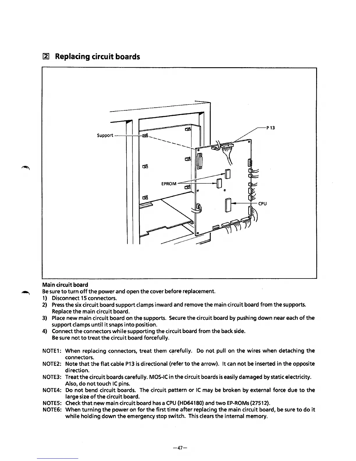
Main circuit board
Be
sure
to
turn
off
the
power
and open
the
cover before replacement.
1)
Disconnect
15
connectors.
2)
Press
the
six
circuit board support clamps inward and remove
the
main circuit board from
the
supports.
Replace
the
main circuit board.
3)
Place
new
main circuit board on the supports. Secure the circuit board by pushing
down
near each
of
the
support clamps
until
it
snaps
into
position.
4)
Connect
the
connectors
while
supporting
the
circuit board from
the
back side.
Be
sure
not
to
treat
the
circuit board forcefully.
NOTE1:
When replacing connectors,
treat
them
c~refully.
Do
not
pull on
the
wires when detaching
the
connectors.
NOTE2:
Note
that
the
flat
cable
P13
is
directional {refer
to
the arrow).
It
can
not
be inserted in
the
opposite
direction.
NOTE3:
Treat
the
circuit boards carefully.
MOS-IC
in
the
circuit boards
is
easily damaged by static electricity.
Also,
do
not
touch
IC
pins.
NOTE4:
Do
not
bend circuit boards. The circuit pattern
or
IC
may
be
broken by external force due
to
the
large size
of
the
circuit board.
NOTES:
Check
that
new
main circuit board
has
a
CPU
{HD64180) and
two
EP-ROMs{27512).
NOTE6:
When
turning
the
power
on
for
the
first
time
after
replacing
the
main circuit board, be sure
to
do
it
while
holding
down
the
emergency stop switch. This clears
the
internal memory.
-47-