7-10
Confidential
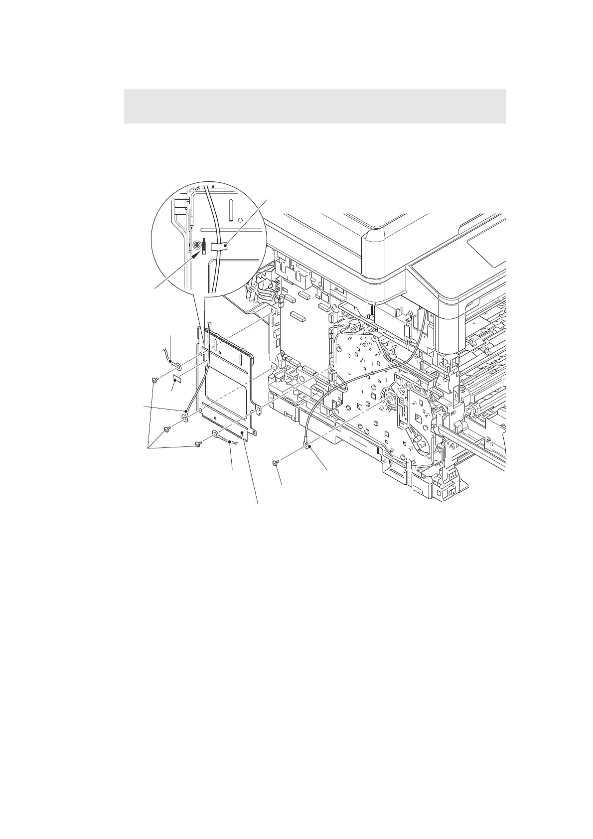
(7) Remove the tape to remove the modem FG harness L from the main shield plate.
(8) Remove the three screw cup M3x8 screws (Black), and remove the ADF FG harness,
FB FG harness, modem FG harness L and main shield plate.
(9) Remove the taptite cup S M3x8 SR screw, and remove the panel FG harness.
Fig. 7-13
Harness routing: Refer to “1. ADF unit - Main PCB ASSY”, “2. Document scanner unit -
Main PCB ASSY”.
Assembling Note:
• Attach the modem FG harness L on the right side than “A” using a tape.
Panel FG harness
Taptite cup S M3x8 SR
Screw cup M3x8
(Black)
ADF FG harness
Modem FG
harness L
Main shield plate
FB FG harness
Tape
“A”
Tape
 Loading...