63
ZTKS0162 / Z31928 / 04
Appendix
A.2 Figures
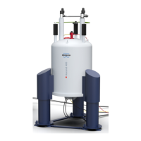
Figure 1.1: General View of a Magnet System with 2 Helium Turrets ................... 12
Figure 2.1: Safety Devices of the Cryostat with 2 Helium Turrets.......................... 26
Figure 3.1: Packaging (without surrounding panels).............................................. 29
Figure 3.2: Transportation by Forklift - front side ................................................... 31
Figure 3.3: Transportation by Forklift - rear side .................................................... 31
Figure 3.4: Attachment Points for Lifting Equipment.............................................. 32
Figure 3.5: Instruction Label for Lifting Equipment................................................. 32
Figure 5.1: Start the Magnet Stand ........................................................................ 38
Figure 5.2: Stop the Magnet Stand ........................................................................ 38
Figure 6.1: Quench Picture .................................................................................... 53
Figure A.1: Dimension Cryostat - Front View ......................................................... 70
Figure A.2: Dimension Cryostat - Top View ........................................................... 72
Figure A.3: Nitrogen Level Graph........................................................................... 74
Figure A.4: Helium Level Graph ............................................................................. 75
Figure A.5: Nitrogen Level Sensor ......................................................................... 76
Figure A.6: Helium Level Sensor............................................................................ 77
Figure A.7: Characteristic Curve PT 100................................................................ 78
Figure A.8: Characteristic Curve IBT...................................................................... 79
Figure A.9: Fringe Field Plot................................................................................... 81
Figure A.10: Current Lead 55 pins ........................................................................... 83
Figure A.11: Wiring Diagram Magnet ....................................................................... 84
Figure A.12: Wiring Diagram Magnet - Control ........................................................ 85
Figure A.13: Wiring Diagram Magnet - Diagnostic and Temperature Sensors ........ 86
Figure A.14: Shorting Plug 55 pins........................................................................... 87
 Loading...
