Do you have a question about the Bruker Anton Paar and is the answer not in the manual?
Provides general information and guidelines for safe operation and product protection.
Specifies requirements for personnel authorized to set up, operate, maintain, and repair the equipment.
Defines proper use of the device and its components, and consequences of improper use.
Outlines limitations of the manual's agreement with hardware/software and welcomes suggestions.
Warns about extreme temperatures and touching internal components or sample holder.
Explains symbols and information signs found on the instrument for safety.
Categorizes heating/cooling devices and describes features of direct heaters.
Discusses methods and sensors for temperature measurement.
Details temperature sensor types (Si-diodes, Pt100, Thermocouples) used for different ranges.
Explains methods to eliminate errors by using standards like MgO or phase transitions.
Describes using MgO as a calibration standard based on its thermal expansion coefficient.
Lists samples with structural phase transitions useful for temperature calibration.
Details the installation of the Edwards turbomolecular pump and its components.
Step-by-step guide for connecting vacuum tubes and mounting the pump.
Instructions for operating the Turbo Instrument Controller (TIC) for vacuum stage control.
Describes the installation of an Edwards backing pump for lower vacuum applications.
General alignment procedures for Anton Paar chambers on the D8 goniometer.
Step-by-step guide for chamber alignment using a dedicated alignment slit.
Procedure for chamber alignment when no specific alignment slit is available.
Details how to implement automated height correction for thermal expansion.
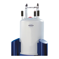
Overview of Anton Paar temperature chambers and their operational similarities.
Describes the procedure for mounting various Anton Paar chambers onto the goniometer.
Introduces TCU and CCU series temperature controllers for Anton Paar chambers.
Details the physical serial line connections for the TCU controller.
Guidance on configuring chambers within the DIFFRAC.MEASUREMENT CENTER software.
Provides operational notes, including warnings for heater shielding and vacuum requirements.
Refers to the general alignment method described in 'Adjustment of a Chamber on the D8'.
Describes the CHC plus chamber's capabilities for humidification and temperature control.
Explains that mounting is similar to other chambers, referring to chapter 5.
Details the TCU/CCU controllers and water bath required for CHC plus operation.
Describes the serial line connections for the CCU controller to the Universal IO-Board.
Details the connections for the MHG (Modular Humidity Generator) controller.
Guidance on configuring the CHC plus chamber in the measurement software.
Provides operational notes, including vacuum and inert gas requirements.
Refers to the general alignment method described in 'Adjustment of a Chamber on the D8'.
Introduces the DCS 350 (Cooling Stage) and DHS 1100 (Hot Stage) chambers.
Describes the mounting procedure for DCS 350 and DHS 1100 stages onto the goniometer.
Identifies TCU and CCU controllers used with DCS 350 and DHS 1100 chambers.
Guidance on configuring DCS 350 and DHS 1100 chambers in the measurement software.
Basic operation steps for the DCS 350 and DHS 1100 chambers.
Manual activation procedure for domed stages within the DA VINCI software.
Describes alignment for domed stages, differing slightly from standard stages.
Procedure for aligning chambers mounted on Eulerian cradles for automated height correction.
Introduces the BTS 150/500 as compact XRD non-ambient stages.
Details the mounting procedure for BTS 150/500 chambers onto the diffractometer.
Explains connecting the BTS 150/500 via USB cable to the CPU1 board.
Guidance on configuring BTS 150/500 chambers in the measurement software.
Refers to operation and alignment procedures described in earlier chapters.
Details on vacuum equipment, including programming the Edwards High Vacuum Stage.
Procedure for resetting the Edwards TIC controller to factory defaults and programming it.
Procedure for configuring various Anton Paar chambers in the measurement software.
Configuration steps for HTK, TTK, XRK, and HPC chambers in the software.
Configuration details for the CHC plus chamber.
Configuration for CHC plus with TCU 110 controller and HE-4 water bath.
Configuration for CHC plus with CCU100 controller and Corio water bath.
Configuration procedure for DCS 350 and DHS 1100 stages.
Configuration steps for BTS 150 and BTS 500 chambers.
Lists the documentation and manuals referenced in this user manual.
| Brand | Bruker |
|---|---|
| Model | Anton Paar |
| Category | Laboratory Equipment |
| Language | English |