50
Fig. 64 — Outdoor-Air Damper Leakage
DIFFERENTIAL DRY BULB CONTROL
For differential dry bulb control, the standard outdoor dry bulb
sensor is used in conjunction with an additional accessory dry bulb
sensor (part number CRTEMPSN002A00). The accessory sensor
must be mounted in the return airstream. (See Fig. 65.) Wiring is
provided in the EconoMi$er IV wiring harness.
In this mode of operation, the outdoor-air temperature is compared
to the return-air temperature and the lower temperature airstream
is used for cooling. When using this mode of changeover control,
turn the enthalpy setpoint potentiometer fully clockwise to the D
setting. (See Fig. 63.)
Fig. 65 — Return-Air Temperature or Enthalpy Sensor
Mounting Location
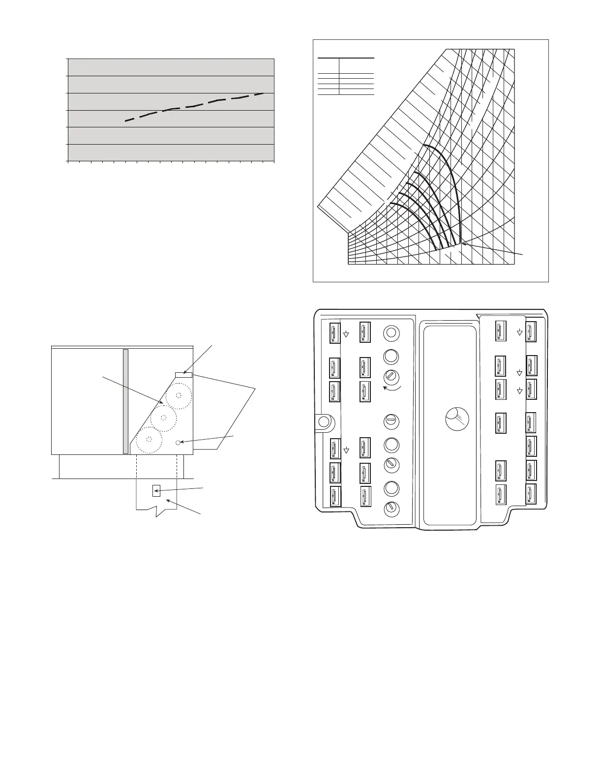
OUTDOOR ENTHALPY CHANGEOVER
For enthalpy control, accessory enthalpy sensor (part number
HH57AC078) is required. Replace the standard outdoor dry bulb
temperature sensor with the accessory enthalpy sensor in the same
mounting location. (See Fig. 66.) When the outdoor air enthalpy
rises above the outdoor enthalpy changeover setpoint, the outdoor-
air damper moves to its minimum position. The outdoor enthalpy
changeover setpoint is set with the outdoor enthalpy setpoint po-
tentiometer on the EconoMi$er IV controller. The setpoints are A,
B, C, and D. (See Fig. 67.) The factory-installed 620-ohm jumper
must be in place across terminals SR and SR+ on the EconoMi$er
IV controller.
Fig. 66 — Enthalpy Changeover Setpoints
Fig. 67 — EconoMi$er IV Control
DIFFERENTIAL ENTHALPY CONTROL
For differential enthalpy control, the EconoMi$er IV controller
uses two enthalpy sensors (HH57AC078 and CRENT-
DIF004A00), one in the outside-air duct and one in the return-air
duct. The EconoMi$er IV controller compares the outdoor air en-
thalpy to the return air enthalpy to determine EconoMi$er IV use.
The controller selects the lower enthalpy air (return or outdoor) for
cooling. For example, when the outdoor air has a lower enthalpy
than the return air, the EconoMi$er IV opens to bring in outdoor
air for free cooling.
Replace the standard outside air dry bulb temperature sensor with
the accessory enthalpy sensor in the same mounting location. See
Fig. 53. Mount the return air enthalpy sensor in the return air duct.
See Fig. 65. Wiring is provided in the EconoMi$er IV wiring har-
ness. See Fig. 58. The outdoor enthalpy changeover setpoint is set
with the outdoor enthalpy setpoint potentiometer on the
EconoMi$er IV controller. When using this mode of changeover
0
5
10
15
20
25
30
0.13 0.20 0.22 0.25 0.300.350.40 0.45 0.50
STATIC PRESSURE (in. wg)
FLOW IN CUBIC FEET PER MINUTE (cfm)
ECONOMI$ER IV
ECONOMI$ER IV
CONTROLLER
GROMMET
RETURN AIR
SENSOR
RETURN DUCT
(FIELD-PROVIDED)
CONTROL
CURVE
A
B
C
D
CONTROL POINT
APPROX.
deg. F (deg. C)
AT 50% RH
73 (23)
70 (21)
67 (19)
63 (17)
1
2 1
4
1
6
1
8
20
2
2
2
4
2
6
28
3
0
32
3
4
3
6
38
40
4
2
4
4
46
9
0
1
0
0
80
7
0
60
50
4
0
30
2
0
1
0
E
NTHALPY BTU PER POUND DRY AIR
85
(29)
90
(32)
95
(35)
100
(38)
105
(41)
110
(43)
35
(2)
35
(2)
40
(4)
40
(4)
105
(41)
110
(43)
45
(7)
45
(7)
50
(10)
50
(10)
55
(13)
55
(13)
60
(16)
60
(16)
65
(18)
65
(18)
70
(21)
70
(21)
75
(24)
75
(24)
80
(27)
80
(27)
85
(29)
90
(32)
95
(35)
100
(38)
A
A
B
B
C
C
D
D
RELA
TI
VE HUMIDITY (
%
)
HIGH LIMIT
CURVE
APPROXIMATE DRY BULB TEMPERATURE--degrees F (degrees C)
TR1
24 Vac
COM
TR
24
Vac
HOT
12
3
4
5
EF
EF1
+
_
P1
T1
P
T
N
EXH
2V 10V
EXH
Set
Set
2V 10V
2V 10V
DCV
DCV
Free
Cool
B
C
A
D
SO+
SR+
SR
SO
AQ1
AQ
DCV
Min
Pos
Open
Max
N1