C−LRV lift control valve Product description
13/92
300−I−9010212−E−10/08.08
1.3.2 Factory settings
All valves are factory−set to the values for the particular installation and
then tested.
S Pressure−relief valve set to the maximum working pressure
S Bypass pressure as per the calculated minimum static pressure
S Mechanical null point of the feedback sensor
S Emergency−lowering valve set to 5−10% of maximum DOWN speed
1.3.3 Description of function
The lift control valve can be subdivided into 3 main functions.
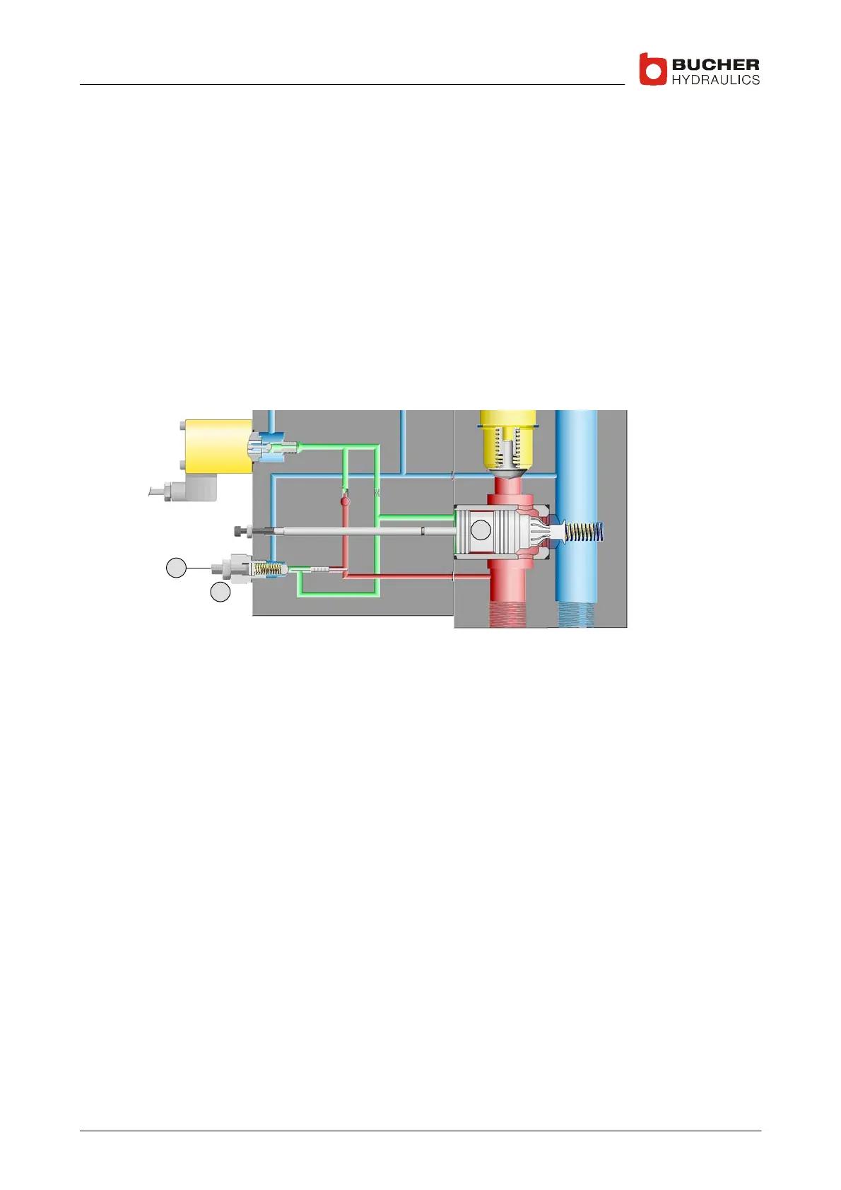
1. Up section / pressure−relief valve
4
16
1
S Initial position:
UP spool (16) is open in the 0 position; pump flow goes directly to
tank
S Up travel / acceleration:
UP spool (16) is progressively closed by the electro−proportional
valve (UP solenoid); this results in smooth acceleration of the lift up to
maximum speed
S Deceleration:
UP spool (16) is progressively opened by the electro−proportional
valve (UP solenoid); this results in smooth deceleration of the lift to
standstill
S Overload:
pressure−relief valve (4) and UP spool (16) open when the maximum
working pressure set with screw (1) is reached
 Loading...
